DOMINO HOBS C621 & C721 INSTALLATION AND OPERATING INSTRUCTION BOOKLET IMPORTANT: You must read this instruction Book before installing or using this appliance and retain it for future use. Caple Products Telephone 0870 2411142 Facsimile 0117 982 6878 Page 1 C621 C721 user manual.
The manufacturer cannot be held responsible for possible inaccuracies due to printing or transcription errors in this booklet. The manufacturer reserves the right to make all modifications to its products deemed necessary for manufacture or commercial reasons at any moment and without prior notice, without jeopardising the essential functional and safety characteristics of the appliances. Dear Customer Thank you for purchasing our product.
Do not leave inflammable material on the cook top. • Make sure that the electrical cables of other appliances installed nearby cannot come into contact with the cook top. • Never cook the food directly on the electric hotplates, but in suitable pans or containers. • IMPORTANT PRECAUTIONS AND RECOMMENDATIONS FOR USE OF ELECTRICAL APPLIANCES Use of any electrical appliance implies the necessity to follow a series of fundamental rules.
" 2 ELECTRIC" COOKING HOB (Fig. 1.3) Electrical insulation Class I. Overheating surfaces protection Type Y. 1. Electrical plate Q) 145 - (1000 W - 1500 W) 2. Electrical plate 0 180 - (1500 W - 2000 W) 3. Electrical plate 1 control knob 4. Electrical plate 2 control knob 5. Power indicator light GAS BURNERS Gas flow to the burners is adjusted by turning the knobs (illustrated in fig. 2.1 b) which control the safety valves.
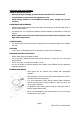
CHOICE OF BURNER (fig. 2.4) The symbols printed on the panel beside the gas knobs indicate the correspondence between the knob and the burner. The most suitable burner is to be chosen according to the diameter and volume capacity of the container to be warmed. It is important that the diameter of the pots or pans suitably match the heating potential of the burners in order not to jeopardize the efficiency of the burners, bringing about a waste of gas fuel.
PROPER USE OF THE ELECTRIC HOTPLATE (fig. 3.3) When the pan comes to the boil, turn the heat down to the level desired. • Remember that the hotplate will continue to produce heat for about five minutes after it has been turned off.
CLEANING AND MAINTENANCE GENERAL RECOMANDATION • Before you begin cleaning you must ensure that the hob is switched off. • It is advisable to clean when the appliance is cold. • Avoid leaving alkaline or acid substances (lemon juice, vinegar etc.) on the surfaces. STAINLESS STEEL ELEMENTS • Stainless steel parts must be rinsed with water and dried with a soft and clean cloth or with a chamois leather.
CORRECT REPLACEMENT OF THE BURNERS It is very important to check that the burner flame distributor “F” and the cap “C” has been correctly positioned (see figs. 5.2 and 5.6 ) failure to do so can cause serious problems. Check that the electrode "S" (fig. 5.2) is always clean to ensure trouble-free sparking. Check that the probe "T" (fig. 5.2) next to each burner is always clean to ensure correct operation of the safety valves. Both the probe and ignition plug must be very carefully cleaned.
INSTALLATION ADVICE IMPORTANT • The appliance should be installed, regulated and adapted to function with other types of gas by a QUALIFIED INSTALLATION TECHNICIAN. • Failure to comply with this condition will render the guarantee invalid. • The appliance must be installed in compliance with regulations in force. • Installation technicians must comply to current laws in force concerning ventilation and the evacuation of exhaust gases.
WITH CUPBOARD DOORS (fig. 6.3) The fixture has to be made according to specific requirements in order to prevent the gas burners from going out, even when the flame is turned down to minimum, due to pressure changes while opening or closing the cupboard doors. It is recommended that a 30 mm clearance be left between the cooker top and the fixture surface beneath it. FASTENING THE COOKTOP (fig. 6.
DISCHARGING PRODUCTS OF COMBUSTION Extractor hoods connected directly to the outside must be provided, to allow the products of combustion in the gas appliance to be discharged (fig. 6.6). If this is not possible, an electric fan may be used, attached to the external wall or the window; the fan should have a capacity to circulate air at an hourly rate of 3-5 times the total volume of the kitchen (fig. 6.7).
FASTENING THE COOKTOP Each cooker top is provided with an installation kit including brackets and screws for fastening the top to fixture panels from 20-30 to 40 mm thick, figs. 6.11 (2 electrical plates hob. • Cut the unit. • Stretch gasket "D" over the edge of the hole made, being careful to overlay the junction edges • Turn the cook top over and put tabs "A" (fig. 6.10) into the mountings, only tighten screws "B" a few turns. Make sure that the tabs are mounted correctly as shown in the figures 6.
Connecting to gas mains: The cook top connection (fig. 7.1 a - 7.1 b) is made up as follows: • 1 nipple "A" • 1 union elbow "C" • gaskets "F" • 1 conical elbow "G" Connection to the gas main must be performed by a qualified technician, in compliance with the current laws in force. Before connecting the appliance to the gas main, mount conical elbow "G" (supplied with appliance) onto the union elbow "C," upon which the gasket "F" has been placed.
INJECTORS TABLE Cat II 2H3+ NOMINAL REDUCED POWER BURNERS [Hs - Kw] POWER [Hs - Kw] G30/G31 G20 28-30/37 mbar 20 mbar Injector dial. Burners with [1/100 mm] Safety valve device Burners without safety valve device By-pass [1/100 mm] By-pass [1/100 mm] Injector dial.
On gas valves provided with adjustment screw on the valve body (fig. 7.6): • Turn the screw "A" to the correct setting with a screwdriver. For G 30/G 31 gas, tighten the adjustment screw completely. LUBRICATING THE GAS TAPS If one of the gas taps becomes difficult to turn, dismantle it, thoroughly clean with petrol and apply special high-temperature grease. These operations must be performed by a specialist engineer.
• The power supply cord must not touch against any hot surfaces and must be placed so that it’s temperature does not exceed 75°C at any point along it’s length. • After having installed the appliance, the power switch or power plug must always be in a accessible position. • The appliance must have its own supply; any other appliances installed near it must be supplied separately. N.B.
REPAIRS REPLACING THE POWER SUPPLY CABLE For 2 electrical plate model Turn the cook top over and unhook the terminal board cover by inserting a screwdriver into the two hooks "A" (fig. 8.1). Open the cable gland by unscrewing screw "F" (fig. 82), unscrew the terminal screws and remove the cable. The new supply cable, of suitable type and section, is connected to the terminal board following the diagram fig. 8.3.
CAPLE "Built-in" Service Should you require service at any time, please contact the Caple Help line on 0870 2411142. Caple have a nationwide service network of engineers who will respond quickly to your call. Always replace spare parts with genuine Caple spares. These are available from authorised Caple Service Centers or by mail order from our National Service Stores, simply telephone 0870 2411142. When ordering parts always quote the model number and serial number of your appliance.