Caprice Model Numbers: C85-340 Version Date: 2013-11-20 NEW – OUTDOOR SENSOR Meets Sept. 2012 requirements for “Automatic Means” INSTALLATION AND OPERATION INSTRUCTIONS CAPRICE OIL BOILER Venting Applications: Natural Draft or Direct Vent (Balanced Flue) TABLE OF CONTENTS 1.0 INTRODUCTION ................................................................................................................ 3 2.0 SPECIFICATIONS ......................................................................................
Caprice │ Installation and Operation Instructions C 85-340 Read Before Proceeding If you do not follow these instructions exactly, a fire may result causing property damage, serious injury or death. FOR YOUR SAFETY, READ BEFORE OPERATING_ BEFORE OPERATING: A. Do not start burner unless the smoke hood, clean out door, HydroStat 3250, flue breeching, and burner door (if applicable) are secured in place and the boiler is filled with water. B.
Introduction - Installation & Operation Instructions │ Caprice C 85-340 1.
Caprice │ Installation and Operation Instructions - Introduction C 85-340 Natural Draft Applications Natural Draft Applications - All Caprice models are certified as Natural Draft boilers which require a “Chimney System”. The exhaust gases must be vented directly to the chimney. Failure to follow these instructions will result in serious injury or death.
Introduction - Installation & Operation Instructions │ Caprice C 85-340 Direct Vent Applications There are four Caprice models, C95-C150, certified for installation as a Direct Vent boiler. This balanced flue system requires a special venting system in order to pressurize and essentially equalize the inlet and outlet pressure to ensure normal operation. Refer to section “General Venting” and “Specifications” for more details on Direct Vent applications and termination kits.
Caprice │ Installation and Operation Instructions - Boiler Location C 85-340 2.0 SPECIFICATIONS Natural Draft Application Draft Settings (Natural Draft) - The Caprice is designed to operate with -.03” w.c. draft in the flue breaching. For proper operation, there must be enough natural or mechanical draft. Due to the design of the Caprice, it may operate at a positive over fire pressure up to +.20 at -.03 draft.
Introduction - Installation & Operation Instructions │ Caprice C 85-340 Direct Vent Application Draft Settings (Direct Vent) - Due to the design of the balanced flue system, the Caprice will operate at a positive draft pressure and a positive over fire pressure at all times. It is designed to operate with a maximum stack draft of 0.25” w.c. and a maximum over fire draft of 0.33” w.c. when little or no wind is present. In extreme wind conditions, the maximum stack draft is 0.35” w.c.
Caprice │ Installation and Operation Instructions - Boiler Location C 85-340 3.0 BOILER LOCATION In all cases, the Caprice must be installed indoors in a dry location where the ambient temperature must be maintained above freezing and below 100F [38C]. All boiler components must be protected from dripping, spraying water, or rain during operation and servicing. Consider the proximity to the following when determining the best boiler location.
Boiler Assembly - Installation & Operation Instructions │ Caprice C 85-340 4.0 BOILER ASSEMBLY The installation of the boiler shall be in accordance with the authorities having jurisdiction and must comply with Standard CSA B139 (Canada) or NFPA 31 (USA). Fiberglass Materials - Before installing the insulated jacket, read “Handling Instructions” in Section 11.0 and the protective measures recommended when handling fiberglass. Jacket Installation 1.
Caprice │ Installation and Operation Instructions - Boiler Assembly C 85-340 Burner Installation The Caprice boiler is designed to work with burners described in this manual. The use of other nozzles, and/or burners, may cause unsafe operation and will void any and all responsibility by NY Thermal for the safety and reliability of the system. The burner kit should be installed in accordance with the instructions in this manual and the burner manufacturer’s instructions included with the burner.
C 85-340 Boiler Assembly - Installation & Operation Instructions │ Caprice Figure 4-5 Burner Installation Set insertion depth (Tables 2-1 to 2-4) Blast Tube Ring Burner Gasket Burner Flange Washers and Nuts Blast Tube Burner Prepare the burner as per the burner manufacturer’s instructions. Refer to Tables 2-1 to 2-4 for nozzle sizes, burner settings, insertion depths, air settings, and specifications.
Caprice │ Installation and Operation Instructions - General Venting C 85-340 5.0 GENERAL VENTING Natural Draft Applications Caprice models C85-340 are certified as Natural Draft boilers. The Natural Draft installation draws combustion air from the room and uses the stack effect and draft system to exhaust flue gases using a chimney. Air Supply - Allowances for combustion air must be supplied to the appliance space, due to the fact that the heating appliance consumes large volumes of combustion air.
C 85-340 Natural Draft - Installation & Operation Instructions │ Caprice 6.0 NATURAL DRAFT APPLICATIONS Natural Draft Rules and Guidelines 1. Acceptable Venting Material - Use vent material approved by National Standards NFPA 31 (USA) or CSA B139 (Canada) and local codes. 2. Venting Application - Venting must be connected to a chimney for models operating with Natural Draft. 3. Chimney Condition - Inspect existing chimney before installing new boiler.
Caprice │ Installation and Operation Instructions - Natural Draft C 85-340 Sizing Combustion Air Openings The following sections detail the three (3) methods for determining the minimum opening size and location required for providing combustion air: 1. Indoor Air - Opening Sizes: Older buildings typically have sufficient ventilation due to air leakage around single pane windows, poorly weather-stripped doors, and non-existent vapour barrier.
C 85-340 Natural Draft - Installation & Operation Instructions │ Caprice Connect Breeching & Blocked Vent Switch Restrictions - Use the minimum vent length and number of elbows possible to ensure flow of combustion gases are not restricted. Failure to follow instructions may result in severe personal injury or death. Blocked Vent Switch - For complete installation details, refer to the manufacturer’s instructions included with the Blocked Vent Switch.
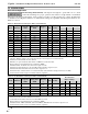
Caprice │ Installation and Operation Instructions - Natural Draft Table 6-1 Minimum Chimney Sizes Minimum Minimum I=B=R Chimney Model Breaching Rectangular Round Diameter C85 C95 1 C105 5" 6" 8" x 8" C125 C150 C180 1 6" 7" 8" x 8" C220 C230 1 8" x 8" C250 7" 8" C275 2 8 " x 12 " C305 2 8" 10 " C340 8 " x 12 " C 85-340 Minimum Chimney Height Boiler Flue Collar Size 15 ' 6" 15 ' 6" 8" 15 ' 8" 20 ' 8" Notes: 1 6-3/4" x 6-3/4" inside liner. 2 6-1/2" x 10-1/2" inside liner.
C 85-340 Direct Vent - Installation & Operation Instructions │ Caprice 7.0 DIRECT VENT APPLICATIONS Direct Vent Rules and Guidelines 1. Vent Material: Use approved venting material. Refer to Direct Vent Termination Kit in this section. 2. Continuous Vent: The vent must be in one continuous piece with no joints. 3. Balance: Combustion air intake and vent must be installed on the same wall using the specified vent terminal to ensure the system is balanced. 4.
Caprice │ Installation and Operation Instructions - Direct Vent C 85-340 Direct Vent Clearances Table 7-1 is a quick reference table that is to be read in conjunction with the numbered notes in the table, the Direct Venting Rules and Guidelines, and Figure 7-1. The instructions detailed in this section are a combination of Caprice specific and National Code restrictions. Compliance alone doesn’t ensure a satisfactory installation as good common sense must also be applied.
C 85-340 Direct Vent - Installation & Operation Instructions │ Caprice Figure 7-1 Termination Clearance Quick Reference Diagram 19
Caprice │ Installation and Operation Instructions - Direct Vent C 85-340 Direct Vent Termination Kit When installed as a Direct Vent boiler the combustion air-inlet must also be piped directly to the outdoors using the methods described in this section and in accordance with the CSA B139 (Canada) or NFPA 31 (USA) and local code requirements. Venting Options - Due to potential moisture loading (build-up) along the exterior wall, sidewall venting may not be the preferred venting option.
C 85-340 Direct Vent - Installation & Operation Instructions │ Caprice Direct Vent Installation Instructions Vent Location - Under normal operating conditions, the boiler will vent plumes of white flue gases; therefore, code restrictions and potential hazards associated with thru-wall installations should be considered before selecting a location for the Direct Vent terminal. To install the Direct Vent Termination Kit for the balanced flue system, complete the steps listed below in sequence.
Caprice │ Installation and Operation Instructions - Direct Vent C 85-340 Sealing Proper Sealing - This Balanced Flue system will leak if the following sealing procedures are not followed. It’s easier to seal the entire system properly the first time than return at a later date and have to remove the connections to reseal it. The adapters are multi-start, left hand thread, with one thread twice the width of the others.
Direct Vent - Installation & Operation Instructions │ Caprice C 85-340 Seal with silicone where shown. Figure 7 -6 Insulated Flex Important Warning - It is the responsibility of the installing contractor to ensure that: 1. The boiler and venting system are totally sealed from products of combustion. 2. The homeowner is advised of their responsibility of keeping the vent terminal clear of snow and ice. 3. That the home is equipped with a carbon monoxide detector.
Caprice │ Installation and Operation Instructions - Boiler Piping 8.0 C 85-340 BOILER PIPING Boiler Water Pressure - Caprice boilers are intended to solely for use in pressurized closed-loop heating systems operating with a “fill pressure” between 12-15 psi at the boiler outlet and a Relief Valve pressure of 30 psi (maximum working pressure of the boiler). Oxygen Elimination - The Caprice boiler is designed to operate in a pressurized closed-loop heating system, free of air and other impurities.
Boiler Piping - Installation & Operation Instructions │ Caprice C 85-340 Figure 8-1 Near Boiler Piping Central Heat Domestic Hot Water Heating Supply Heating Return Drain Valves (back flushing) Unions (for servicing) Automatic Air Vent Bypass Line (optional) Expansion Tank Coil Outlet Coil Inlet Water Supply Pump * Relief Valve DHW to Fixtures Cold Water Supply Inlet Tempering Valve (mandatory) Isolation / Throttle Valves * Circulator location may vary from one application to another.
Caprice │ Installation and Operation Instructions - Installation Checklist 9.0 C 85-340 FIELD WIRING All wiring and electrical grounding must be in accordance with local codes and the applicable National Electrical Code, NFPA 70 (USA) or CSA C22.2 (Canada). Ensure that the wiring complies with this manual. Avoid Shocks - To Avoid Electrical Shock, turn off electrical power to the boiler prior to opening any electrical box within the unit.
C 85-340 Installation Checklist - Installation & Operation Instructions │ Caprice Figure 9-1 Caprice Wiring Diagram Burner Primary Safety - The Blocked Vent Switch and any other limit device must break power to the burner primary (B1). Failure to follow these instructions may result in serious injury or death.
Caprice │ Installation and Operation Instructions - Installation Checklist C 85-340 Fuel Smart HydroStat Model 3250-Plus The Fuel Smart HydroStat 3250-Plus is manufactured by HydroLevel Company. It is a Temperature Limit and Reset Control for oil and gas fired boilers. It meets the September 2012 requirements for “Automatic Means” of adjusting boiler temperature. The HydroStat provides only temperature and reset functionality when installed on a standard immersion well used on Caprice models.
C 85-340 Installation Checklist - Installation & Operation Instructions │ Caprice LO TEMP: o Minimum permissible boiler temperature, burner will fire without demand when temperature drops below the LO TEMP setting. o Controller inhibits circulator operation (120V outputs at C1 and ZC are deactivated) until the temperature exceeds the LO TEMP setting. o “Tankless Coil” – set LO TEMP to a minimum of 140ºF to obtain DHW priority.
Caprice │ Installation and Operation Instructions - Installation Checklist C 85-340 Inferring Heat Load (“Automatic Means” of Adjusting Boiler Temperature) The HydroStat control incorporates two (2) options for Inferring Heat Load: 1) Thermal Targeting Method – default method 2) Outdoor Reset Method – method used when outdoor sensor is connected to OR and C 1) Thermal Targeting Method: Default method for satisfying central heat demands.
Installation Checklist - Installation & Operation Instructions │ Caprice C 85-340 2) Outdoor Reset Method: Automatically active when the Outdoor Sensor is connected to the OR and C spade connects on the Fuel Smart HydroStat. Outdoor Reset overrides Thermal Targeting Method. The Reset Ratio setting dictates the influence the outdoor temperature has on the boiler target temperature during a central heat demand.
Caprice │ Installation and Operation Instructions - Installation Checklist C 85-340 10.0 INSTALLATION CHECKLIST Start-up 1. Close automatic air vent and boiler drain cock. 2. Boiler water pH range should be 7.0 - 8.5. If conditions are above 7, contact local water treatment company. 3. Fill boiler with water until gauge reads 12-15 psi using auto fill device. Check for leaks. 4. Open automatic air vent 1 turn. 5. Bleed air from system.
Installation Checklist - Installation & Operation Instructions │ Caprice C 85-340 Adjusting Combustion Air Smoke Pump - A reliable, certified smoke pump is required to correctly set up this equipment. Combustion Analyzer - To calibrate burner operation, use a calibrated combustion analyzer capable of measuring CO2 and O2 from oil burning boilers. Smoke Test - All tests must be done with the burner covers or air intakes in place to simulate normal operation.
Caprice │ Installation and Operation Instructions - Maintenance C 85-340 11.0 ANNUAL MAINTENANCE AND INSPECTION The building owner is responsible for scheduling boiler routine maintenance as described in this section. The boiler unit must be inspected at the beginning of every heating season by a Qualified Technician. Annual Inspection Checklist 1. Make sure boiler is filled with water and fill valve is operating properly. 2. Inspect the condition of the combustion chamber. 3.
Maintenance - Installation & Operation Instructions │ Caprice C 85-340 Handling Instructions Fiberglass and Ceramic Fiber Materials - Caprice boilers use insulating materials to reduce casing losses and clearances to combustibles. It is important for installers and service personnel to know what these materials are, where they are located on the boiler, and how they should be handled. Refer to Table 11-1 for recommended handling instructions and Figure 12-1 for location of insulating materials.
Caprice │ Installation and Operation Instructions - Parts List C 85-340 12.0 PARTS LIST For a list of parts that corresponds to the item numbers in the callouts, refer to Table 12-1. Note that some item numbers may appear more than once in the parts list depending on which model number is being referenced. Building Owners - Replacement parts are available from your stocking wholesaler. Contact your local Installer or Wholesaler for assistance with parts. Wholesalers - Contact NY Thermal Inc.
Parts List - Installation & Operation Instructions │ Caprice C 85-340 Figure 12-2 Burner Package Item 21: Burner and blast tube are sold as a fully assembled unit. Included with Burner Kit Burner Gasket 21 Burner Flange 20 19 Washers & Nuts Items 19 & 20: Riello burners and blast tubes are ordered separately, field assembled.
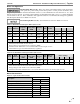
Caprice │ Installation and Operation Instructions - Parts List Table 12-1 Caprice Parts List: Item Part # Models C85-180 1 C85 C220-340 1 C220 C85-340 2 139 C85-340 3 497 C85-340 4 13501 C85-180 5 10152 C220-340 5 10154 C85-340 6 84787 C85-340 7 12501 C85-340 8 81342 C85-340 9 13701 C85-340 10 82905 C85-180 11 134 C220-340 11 150 C85-180 12 133 C220-340 12 149 C85-180 13 132 C220-340 13 593 C85-180 14 141 C220-340 14 147 C85-180 15 135 C220-340 15 151 C85-180 16 137 C220-340 16 148 C85-180 17 503 C220-340 1
13.0 WARRANTY A licensed and trained Heating Technician must install this appliance, otherwise the Warranty is VOID. FREE extended coverage Option C, only IF you register your boiler and installation with NY Thermal Inc. within the first year of purchase. What Is Covered We, the manufacturer, warrant that any parts or components of each new Boiler or Water Heater, will be supplied free of defects in material or workmanship. This warranty replaces any other warranty implied or expressed.
OR with Outdoor WWSD Reset overridesCaprice │ Installation and Operation Instructions - Parts List Thermal Targeting. What To Do In The Case of A Warranty Service Problem C 85-340 1. Contact your installing contractor or service provider. Do not call NTI. 2. If your contractor or service representative requires further help, they will contact us directly. 3. If you cannot contact your contractor or service representative, contact us at 1-506-657-6000 to the attention of the Service Department.