
User's Manual


PARTS & SPECIFICATIONS
TOOLS REQUIRED
Phillips Screw Driver
Flat Head Screwdriver
Drill (Option 2 only)
Drill Bit 7mm (9/32”) (Option 2 only)
Ladder
Level
Safety Goggles
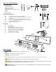
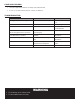
HARDWARE INCLUDED
AA 2 – Mounting Plate Screws (Pre-installed)
BB 2 – #8-32 x 1” Electrical Box Mounting Screws (Option 1)
CC 2 – Wire Nuts
DD 2 – Capstone Quick Connector (1 Pre-wired; 1 Loose)
EE 2 - #4 x 1” Self-Tapping Wall Mounting Screws (Option 2)
FF 2 – Plastic Wall Anchors (Option 2)
GG 1 – White Cleaning Cloth
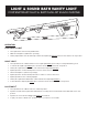
DIAGRAM
A Light Fixture
B Mounting Plate
C Electrical Box Screw Hole (Option 1)
D Wall Mounting Screw Holes (Option 2)
E Ground Screw (Green, Pre-installed)
AA Mounting Plate Screws (Pre-installed)
F ON/OFF Rocker Switch
G Electrical Box (not included)
AA BB
EE
CC
FF
DD
GG
A
D
B
AA
AA
E
F
G
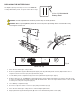
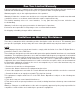
INSTALLATION
IMPORTANT: This fixture has two installation options.
OPTION 1 – ANCHOR TO AN ELECTRICAL BOX
OPTION 2 – ANCHOR TO A WALL
Both OPTION’s require powering the xture using a standard 4” octagonal recessed electrical box (G).
WARNING: Consult a qualified electrician if you have any electrical questions.
WARNING: Before starting installation of this fixture or removal of an existing fixture disconnect the power
by turning off the circuit breaker or by removing fuse at fuse box.
IMPORTANT: Notice the position of cutouts on the Mounting Plate. Cutouts must be positioned correctly
for proper mounting.
Bottom
C