www.excalibur-fire.com P90 Zero Clearance Direct Vent Gas Fireplace MODELS: P90-NG1 Natural Gas Owners & Installation Manual P90-LP1 Propane WARNING: If the information in these instructions are not followed exactly, a fire or explosion may result causing property damage, personal injury or loss of life. FOR YOUR SAFETY What to do if you smell gas: Do not try to light any appliance Do not touch any electrical switch: do not use any phone in your FOR YOUR SAFETY building.
To the New Owner: Congratulations! You are the owner of a state-of-the-art Excalibur® Gas Fireplace by FPI FIREPLACE PRODUCTS INTERNATIONAL LTD. The P90 is a hand crafted appliance and has been designed to provide you with all the warmth and charm of a wood fireplace at the flick of a switch. The model P90 has been approved by Warnock Hersey for both safety and efficiency. As it also bears our own mark, it promises to provide you with economy, comfort and security for many trouble free years to follow.
TABLE OF CONTENTS SAFETY LABEL Serial No. Decal ..........................................................4 REQUIREMENTS MA Code - CO Detector (for state of Massachusetts only) ..................................5 Glass Door Installation ................................................31 Arch Surround .............................................................31 Optional Screen Door .................................................31 Accent Kit Installation ..............................................
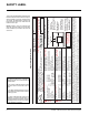
This is a copy of the label that accompanies each P90 Zero Clearance Direct Vent Gas Fireplace. We have printed a copy of the contents here for your review. The safety label is located on the front inside base of the unit, visible when the bottom louver is open. For the State of Massachusetts, flexible connectors shall not exceed 36 inches in length. For the State of Massachusetts, the appliances individual manual shut-off must be a t-handle type valve.
REQUIREMENTS MA Code - CO Detector (for the State of Massachusetts only) 5.08: Modifications to NFPA-54, Chapter 10 (2) Revise 10.8.
INSTALLATION IMPORTANT MESSAGE SAVE THESE INSTRUCTIONS The P90-NG1 or P90-LP1 Direct Vent Fireplace must be installed in accordance with these instructions. Carefully read all the instructions in this manual first. Consult the "authority having jurisdiction" to determine the need for a permit prior to starting the installation. It is the responsibility of the installer to ensure this fireplace is installed in compliance with manufacturer's instructions and all applicable codes.
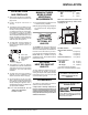
INSTALLATION LOCATING YOUR GAS FIREPLACE 1) When selecting a location for your fireplace, ensure that the clearances outlined on this page are met. MANUFACTURED MOBILE HOME ADDITIONAL REQUIREMENTS 2) P r o v i d e a d e q u a t e c l e a r a n c e s f o r servicing. 1) Ensure that structural members are not cut or weakened during installation. 3) The appliance must be installed on a flat, solid, continuous surface (e.g. wood, metal, concrete).
INSTALLATION COMBUSTIBLE MANTELS FRAMING AND FINISHING Because of the extreme heat this fireplace emits, the mantel clearances are critical. Combustible mantel clearances from top of unit are shown in Diagram below. 1) Determine the total thickness of facing material (e.g. drywall plus ceramic tiles) to allow the finished surface to be flush with the front of the unit. Total facing thickness can vary from 1/2" (13mm) to 1" (32mm) thick.
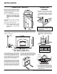
INSTALLATION 4) Note: The unit does not have to be completely enclosed in a chase. The clearance on top of the unit is 0" to the standoffs so combustible building materials can be laid directly on top of the standoffs. You must maintain clearance from the vent to combustible materials for both rigid and flex, see the "Clearances" section. Facing Over 1" (25mm) Thick If the facing material is over 1" (25mm) thick (example: brick or river rock), install the facing around the perimeter of the face.
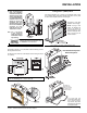
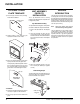
INSTALLATION OPTIONAL COVER PLATE TEMPLATE 1) Ensure top clip screws are at top of oblong holes before installation. Oblong Screw Holes UNIT ASSEMBLY PRIOR TO INSTALLATION The 2 Top Standoffs must be correctly positioned and attached to the top before unit is slipped into position. Top Standoff Assembly The top standoffs are shipped in a flat position and must be folded into shape and attached. 1) Remove the standoffs from the fireplace top.
INSTALLATION VENTING FPI Direct Vent System (Flex) Horizontal Terminations Only These venting systems, in combination with the P90 Direct Vent Gas Fireplace, have been tested and listed as a direct vent heater system by Warnock Hersey. The location of the termination cap must conform to the requirements in the Vent Terminal Locations diagram in the "Exterior Vent Termination Locations" section.
H= Not to be installed above a meter/regulator assembly within (3'/90cm) horizontally from the centerline of the regulator. J= Clearance to service regulator vent outlet *(min 36"/90cm) K= Clearance to non-mechanical air supply inlet to building or the combustion air inlet to any other appliance *(12"/30cm) #(9"/23cm) L= Clearance to a mechanical air supply inlet *(min. 72"/1.8m) #3' (91cm) above if within 10' (3m) horizontally.
INSTALLATION RIGID PIPE VENTING COMPONENTS LIST All Simpson Dura-Vent components are available directly from FPI.
INSTALLATION RIGID PIPE VENTING SYSTEMS The minimum components required for a basic horizontal termination are: 1 1 1 1 1 1 Flat Wall Installation Horizontal Termination Cap 90o Elbow Rigid Pipe Adaptor Wall Thimble Length of pipe to suit wall thickness (see chart) 4" x 6-5/8" to 5" x 8" increaser for 5" x 8" venting Wall Thickness (inches) Vent Length Required (inches) 4" - 5-1/2" 6" 7" - 8-1/2" 9" 10" - 1-1/2" 12" 9" - 14-1/2" 11" - 14-5/8" Adj. Pipe 15" - 23-1/2" 17" - 24" Adj.
INSTALLATION Horizontal & Vertical Terminations for 5" x 8" Venting Excalibur® P90 Zero Clearance Direct Vent Gas Fireplace 15
INSTALLATION RIGID PIPE VENTING ARRANGEMENTS - HORIZONTAL TERMINATIONS FPI DIRECT VENT SYSTEM (FLEX) (Propane & Natural Gas) The diagram shows all allowable combinations of vertical runs with horizontal terminations, using one 90o elbow (two 45o elbows equal one 90o elbow).
INSTALLATION RIGID PIPE VENTING ARRANGEMENTS - VERTICAL TERMINATIONS The shaded area in the diagram shows all allowable combinations of straight vertical and offset to vertical terminations, using two 90o elbow, with rigid pipe vent systems for Propane and Natural Gas. • • • Vent must be supported at offsets. Firestops are required at each floor level and whenever passing through a wall. Maintain clearances to combustibles.
INSTALLATION The P90 is approved for a maximum 40 ft. straight vertical, with rigid pipe 4" x 6-5/8" vent systems for Propane and Natural Gas, as per diagram. The shaded area in the diagram show all allowable combinations of straight vertical and offset to vertical terminations with rigid pipe vent systems for Propane and Natural Gas. Maximum two 45o elbows allowed. • • Vent must be supported at offsets Firestops are required at each floor level and whenever passing through a wall.
INSTALLATION Horizontal Venting with Two (2) 90o Elbows Must Use: 5" x 8" Simpson Direct Vent GS Piping with FPI Increaser Starter Collar (Part #946-605). One 90o elbow = Two 45o elbows. Option A) B) C) D) E) F) G) V 6" Min. 1' Min. 2' Min. 3' Min. 4' Min. 5' Min. 6' Min. H + H1 2' Max. 3' Max. 4' Max. 5' Max. 6' Max. 7' Max. 8' Max. With these options, maximum total pipe length is 30 feet with minimum of 6 feet total vertical and maximum 8 feet total horizontal.
INSTALLATION Vertical Venting with Two (2) 90o Elbows Must Use: 5" x 8" Simpson Direct Vent GS Piping with FPI Increaser Starter Collar (Part #946-605), unless V1 is greater than or equal to 4'-6" then use 4" x 6-5/8" piping. One 90o elbow = Two 45o elbows. Option A) B) C) D) E) F) V 0' Min. 1' Min. 2' Min. 3' Min. 4' Min. 5' Min. H 2' Max. 4' Max. 5' Max. 6' Max. 7' Max. 8' Max. V + V1 1' Min. 2' Min. 3' Min. 4' Min. 5' Min. 6' Min. With these options, max. total pipe length is 30 feet with min.
INSTALLATION Install the vent system according to the manufacturer's instructions included with the components. 1) Set the unit in its desired location. Check to determine if wall studs or roof rafters are in the way when the venting system is attached. If this is the case, you may want to adjust the location of the unit. Rough in the gas preferably on the right side of the unit and the electrical (junction block is on the left side) on the left.
INSTALLATION 4) Assemble the desired lengths of pipe and elbows. Ensure that all pipes and elbow connections are in the fully twist-locked position and sealed. VERTICAL TERMINATIONS Diagram 5 The four wood screws provided should be replaced with appropriate fasteners for stucco, brick, concrete, or other types of sidings. Note: If installing termination on a siding covered wall, a vinyl siding standoff or furring strips must be used to ensure that the termination is not recessed into the siding.
INSTALLATION the vertical height must be increased. A poor draft, or down drafting can result from high wind conditions near big trees or adjoining roof lines, in these cases, increasing the vent height may solve the problem. 7) Ensure vent is vertical and secure the base of the flashing to the roof with roofing rails, slide storm collar over the pipe section and seal with a mastic. 8) Install the vertical termination cap by twistlocking it.
INSTALLATION P90-NG1 System Data For 0 to 4500 feet altitude Burner Inlet Orifice Sizes: #34 Max. Input Rating Min. Input Rating 35,000 Btu/h 18,200 Btu/h Supply Pressure min.5.0" w.c. Manifold Pressure (High) 3.8"+/- 0.2"w.c. P90-LP1 System Data When using copper or flex connectors use only approved fittings. Always provide a union so that gas lines can be easily disconnected for servicing. Flare nuts for copper lines and flex connectors are usually considered to meet this requirement.
INSTALLATION CONVERSION KIT #791-969 FROM NG TO LP THIS CONVERSION MUST BE DONE BY A QUALIFIED GAS FITTER IF IN DOUBT DO NOT DO THIS CONVERSION !! 4) Each Kit contains one LPG Conversion Kit and one DC Sparker Kit. 9) Turn control knob to the “OFF” position. 10) Remove the black protection cap by hand from the high-low knob (Fig.1). LPG Conversion Kit Contains: Qty.
INSTALLATION 14) Using the Allen wrench as shown in Fig.4, rotate the screw clockwise until snug, do not overtighten. 17) Reverse steps 4) to 2). 4) Attach the DC sparker generator connector to the valve with a screw. 5) Remove the stove’s rear panel by unscrewing the two screws. 6) Attach the ground wire to the grounding stud. 18) Attach clear label "This unit has been converted to LPG" near or on top of the serial # decal. 19) Replace yellow "Natural Gas" label with red "LPG" label.
INSTALLATION 7) Attach the Piezo ignition wire to the DC Sparker. 11) Attach the DC sparker generator wires to the DC sparker. Piezo Ignitor Installation of the DC Sparker for the P90 Units Only: 1) Locate the Piezo Ignitor situated at the side of valve. Piezo Ignitor 12) Install the supplied battery into the DC Sparker Box by opening the battery compartment. 8) Insert both the ground wire and the DC sparker generator wire through the hole of the DC spark heat shield.
INSTALLATION 5) Connect the DC spark generator wires to the SIT Valve with the screw, which is provided in the kit. 9) Run the other end of the ground wire and DC spark generator wires through the bushing on the heat shield. 13) Mount the heat shield to the DC Sparker. Secure into place with the velcro, which is provided in the kit. Heat Shield 14) Find a location which is not too hot and is easy to reach for changing the battery. 6) 10) Plug the DC spark generator wires to the DC Sparker.
INSTALLATION OPTIONAL BRICK PANELS LOG SET INSTALLATION 1) Open the bottom louver door. Loosen the 2 screws holding the Burner ON/OFF switch and bracket to the bottom louver and lift the assembly out. Read the instructions below carefully and refer to the diagrams. If logs are broken do not use the unit until they are replaced. Broken logs can interfere with the pilot operation. 2) Remove Arch Surround.
INSTALLATION 9) Sit Log 02-50 on the front left side of the burner. Push the back of the log against the 2 front brackets with the notch on the bottom of the log fitting into the first grate tab. 10) Place the embers on the front of the burner tray in the places shown on the photos below. 02-50 02-53 7) Place the bottom left front edge of Log 02-55 against the rear bracket on the burner tray and rest the log on the cutout onL o g 02-53. Place embers in these 3 locations on the burner tray.
INSTALLATION GLASS DOOR INSTALLATION OPTIONAL SCREEN DOOR 1) Attach door bracket to side using 2 screws. 1) Fit top door bracket over the flange at the top of the firebox. 2) Secure with 2 screws on the bottom. Tighten both screws to secure Arch Surround to Glass Door. 3) Slide Bottom Louver into position. On each side secure the bottom screw first into the side bracket. Do not overtighten, leave slightly loose to allow the louver to move freely. Then tighten the top screw.
INSTALLATION ACCENT KIT INSTALLATION 1) Remove the rivets from the surround by pulling out the hoseclamp with a screwdriver or plyer. Re-install the rivets by putting them through the holes on the sides of the surround. 5) Remove the 2 studs on the sides of the Hood. Insert the new studs through the holes and secure them by first putting on the washer and then tighten with a nut. DOUBLE & SINGLE DOOR OPTION 2) Take the hoseclamps and put them over the back of each rivet.
INSTALLATION Option 1: REMOTE CONTROL Option 2: WALL SWITCH Option 3: WALL THERMOSTAT Use the Excalibur® Remote Control Kit approved for this unit. Use of other systems may void your warranty. 1) Run the wire through the right or left side gas inlet opening. Be careful not to damage wire. A wall thermostat may be installed if desired, connect the wires as per the wiring diagram. Use the table below to determine the maximum wire length.
INSTALLATION WIRING DIAGRAMS This heater does not require a 120V A.C. supply for operation. In case of a power failure, the burner switch and the optional remote control/ thermostat will continue to operate. NOTE: However, a 120V A.C. power supply is needed for the fan/blower operation. (Do not cut the ground terminal off under any circumstances.
INSTALLATION For PROPANE Units and Units Equipped with DC Spark Boxes* *For installation of the DC Spark Box refer to the LP Conversion instructions in this manual.
OPERATING INSTRUCTIONS OPERATING INSTRUCTIONS 1) Read and understand these instructions before operating this appliance. 2) Check to see that all wiring is correct and enclosed to prevent possible shock. 3) Check to ensure there are no gas leaks. 4) Make sure the glass in the door frame is properly positioned. Never operate the appliance with the glass removed. 5) Verify that the venting and cap are unobstructed. 6) Ensure that the brick panels are installed. 7) Verify log placement.
OPERATING INSTRUCTIONS COPY OF THE LIGHTING PLATE INSTRUCTIONS NORMAL OPERATING SOUNDS OF GAS APPLIANCES It is possible that you will hear some sounds from your gas appliance. This is perfectly normal due to the fact that there are various gauges and types of steel used within your appliance. Listed below are some examples. All are normal operating sounds and should not be considered as defects in your appliance.
MAINTENANCE MAINTENANCE INSTRUCTIONS 1) Always turn off the gas valve before cleaning. For relighting, refer to lighting instructions. Keep the burner and control compartment clean by brushing and vacuuming at least once a year. When cleaning the logs, use a soft clean paint brush as the logs are fragile and easily damaged. 2) Clean appliance and door with a damp cloth (never when unit is hot). Never use an abrasive cleaner. The glass should be cleaned with a gas fireplace glass cleaner.
MAINTENANCE FAN MAINTENANCE To Remove the Fan Unit must be grounded at all times. Do not cut the ground terminal off under any circumstances. 1) Shut the power off. 2) Reverse the above instructions. To Install the Fan Note: The bearings are lubricated for life. Do not lubricate them. Make sure you vacuum the fan area on a regular basis. 1) Shut the power off. 2) Open the bottom louver door. Loosen the 2 screws holding the Burner ON/OFF switch and bracket to the bottom louver and lift the assembly out.
MAINTENANCE REMOVING VALVE Hint: 1) Shut the power off. 2) Open the bottom louver door. Loosen the 2 screws holding the Burner ON/OFF switch and bracket to the bottom louver and lift the assembly out. 3) Remove the facade if installed. 4) Remove the glass door (Refer to the "Glass Door Installation" section). 5) Remove the logs. If you are using black pipe, ensure that there is a union by the valve, otherwise removal will be almost impossible. INSTALLING VALVE 9) Disconnect the inlet gas line. See dia.
PARTS LIST P90 MAIN ASSEMBLY Part # 1) 2) 7) 8) 9) 10) 430-129 * 910-428 910-429 910-430 904-687 Description Receptacle Box Mount Thermodisc Bracket Duplex Receptacle Box - Receptacle Cover - Receptacle Clamp Connector 15) * 20) 790-021 21) 790-022 Heat Shield - Base Front Filler - Left Corner Front Filler - Right Corner 22) 23) 24) 25) 790-012 780-011 780-013 780-091 Baffle Standoff - Top Standoff - Side Standoff - Rear 27) 28) 30) 31) * * * * Outer Flue Collar Inner Flue Collar Assy Gasket for Fl
PARTS LIST 89 HEAT WAVE DUCT KIT 93 94 93 95 92 91 96 50 102 100 31 99 30 97 98 64 90 28 63 30 62 25 23 27 61 25 23 60 59 51 20 61 24 109 61 64 64 22 10 1 108 15 8 7 24 21 HEAT RELEASE DUCT KIT 9 36 2 36 34 32 48 33 BRICK PANELS 49 43 38 ON-OFF SWITCH ASSEMBLY 35 47 42 FAN SWITCH ASSEMBLY 42 Excalibur® P90 Zero Clearance Direct Vent Gas Fireplace
PARTS LIST P90 BURNER ASSEMBLY & LOG SET Part # Description 52) 910-190 53) 780-021 Piezo Ignitor & Nut Gasket - Valve Access Plate 790-574/P 790-576/P 56) * 57) 910-478 58) * 65) * 66) 910-038 910-039 904-617 904-645 936-170 67) * 68) W840470 Valve Assy - Natural Gas Valve Assy - Propane Valve Tray - NG/LP Valve - S.I.T. - NG/LPG Valve Bracket Pilot Bracket Pilot Assy-NG 3 way flame - S.I.T. Pilot Assy-LP 3 way flame - S.I.T.
PARTS LIST P90 FLUSH FRONT ACCESSORIES Part # Description 790-518 132) 790-137 135) 940-326/P 136) 936-155 904-691 141) 142) 143) 144) 145) 146) 148) 149) Part # Door Assembly - Complete Flush Door Frame Glass (Flush) Glass Gasket (Tadpole) U-Clip 790-920 790-922 790-914 790-916 790-918 * * 904-621 790-122 * * 904-719 904-719/G 904-720 161) 162) 163) 164) 167) 168) Surround - Black - Complete Surround - Gold - Complete Surround - Antique Gold - Complete Surround - Antique Nickel - Complete Surround
NOTES ___________________________________________________ ___________________________________________________ ___________________________________________________ ___________________________________________________ ___________________________________________________ ___________________________________________________ ___________________________________________________ ___________________________________________________ ___________________________________________________ ______________________________________
NOTES ___________________________________________________ ___________________________________________________ ___________________________________________________ ___________________________________________________ ___________________________________________________ ___________________________________________________ ___________________________________________________ ___________________________________________________ ___________________________________________________ ______________________________________
WARRANTY Excalibur® Fireplace Products are designed with reliability and simplicity in mind. In addition, our internal Quality Assurance Team carefully inspects each unit thoroughly before it leaves our facility. FPI Fireplace Products International Ltd. is pleased to extend this limited lifetime warranty to the original purchaser of a Excalibur® Product.
Excalibur® fireplace products are designed with reliability and simplicity in mind. In addition, our internal Quality Assurance Team carefully inspects each unit thoroughly before it leaves our door. FPI Fireplace Products International Ltd. is pleased to extend this Limited Lifetime Warranty to the original purchaser of a Excalibur® Product. See the inside back cover for details. Register your Excalibur® online at http://www.excalibur-fire.