Ca bide 3D Shapeoko XL Assembl Guide Unpack Bo ☰
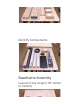
dentif Components Baseframe Assembl La out Cross straps (18 center to center)
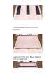
O erla asteboard, install center 3 scre s (M5 25mm) La out Front and Rear Plates, install feet ( 4)
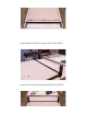
nstall Rear End Plate using 6 M5 25mm BHCS nstall Front End Plate using 6 M5 25mm BHCS
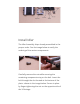
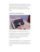
XZ Assembl The X Carriage and Z Carriage are shipped together in the same bo along ith t o small bags that contain t o springs and the dler Assembl . The Z Carriage is the smaller of the t o carriages sho n in the image belo . Carefull remo e the Z Carriage from its protecti e rapping; ensure that the belt is not damaged or remo ed from its initial installation location.
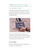
nstall dler The dler Assembl ships alread assembled in the proper order. See the image belo to erif the ordering of the arious components. Carefull remo e the nut hile ensuring the remaining components sta on the bolt. nsert the bolt through the slot located at the bottom of the plate - sho n in the image belo . Secure in place b nger-tightening the nut on the opposite side of the X Carriage.
Once the idler assembl is through the slot, loosel attach the nut on the backside of the plate. Some adjustabilit ill be required to get the belt in place, so lea e this lightl nger tight for the time being. nstall Spindle Mount Align the spindle mount ith the bottom set of through holes on the -carriage. The carbide logo should go right side up, but the position of the pocketed hole on the spindle mount does not matter (left or right is ne).
NO E: f ou ere to install the -carriage back ards ( ith the scre s on the right), the a is ill operate in re erse. Turning the -carriage o er, secure the spindle mount b installing (2 ) of the M5 16mm scre s through the back of the plate and into the rear of the spindle mount. Tighten these scre s do n at this point in the assembl . Using some thread locker ill help keep them secure and reduce the chance of ibration causing the scre s to become loose.
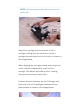
NO E: The bearings and belt ill no be on the underside. Align the -carriage ith the bottom of the - carriage, making sure the eccentrics on the carriage are positioned on the left side, as sho n in the image belo . When aligning the carriages, make sure the groo e in the - heel is aligned carriage. The heels ith -rail on the - ill slide up the V, seating e enl and securel on both sides.
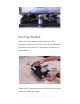
Routing the Belt When the Z Carriage is attached to the rails properl , a portion of the belt should be e iting the top and bottom of the Z Carriage as sho n in the image belo . Slo l pull the bottom portion of the belt and loop it o er the dler as sho n.
The dler can mo e up and do n in its groo e. You ma ha e to loosen the nut to mo e the dler. Carefull rap the upper portion of the belt around the top pulle as sho n.
tension on the belt and nger-tighten again so the belt does not come o the dler. Tension Scre Carefull place the X/Z Carriage on its back (resting on the motor) as sho n in the image belo . Slide the Z Carriage all the a to the top until it stops at the t o posts sho n in the image belo . Ensure that ou ha e onl nger-tightened the dler Assembl before tightening the Tensioning Scre .
Use the he Scre rench to tighten the Tensioning as sho n in the image belo . As the Tensioning Scre is tightened, it ill push on the dler Assembl . The belt should be tight enough that it doesn t slip o the dler and does not e as the carriage mo es up and do n. When the belt is tight, use a 4mm he ke and 10mm rench to tighten the dler Assembl as sho n in the image belo . nstall Springs La the X/Z Carriage on one of its sides as sho n in the image belo .
Pull up on the spring and attach the other loop to the X Carriage post as sho n in the image belo . Turn the X/Z Carriage on its other side and attach second spring in identical manner as sho n in the image belo . Using the 2 M5 55mm scre s, install into spindle mount. Do not tighten at this point, these scre s after this guide.
Carriages La out X-A is e trusion and Y1, Y2, XZ Plates
nstall Y-Left Carriage ### nstall X/Z Carriage nstall Y-Right Carriage
Rail S stem Roughl Position s stem in place (in line, but o set to right side)
Using the foam pads from the Y-left and -right bo es, slide s stem into place and prop up ith pads. Use 1 M6 12mm BHCS in front and rear of right side. Lift left side into place, install 1 M6 12mm BHCS in front and rear.
Belting dentif belting components
Remo e the three belts from their bag. Note that the three belts are of identical length. For all three belt installations, the follo ing process ill be follo ed: 1. One end of each belt clip ill be inserted into a belt ith the teeth do n. The belt is inserted up from the bottom in the gap nearest the end of the clip as sho n in Step 1. 2. The belt is ne t inserted into from the top to the bottom in the second gap as sho n in Step 2. 3.
NO E: The free end of the belt (the end not looped through a belt clip) ill be routed through the carriages and then secured using another belt clip using more detailed steps pro ided belo . X-A is Rail Belt nstallation nsert one end of a belt through the belt clip as described abo e. Ensure that the bottom 2 portion of belt interlocks ith the top portion and secure it to the Y-A is Left Carriage as sho n in the image belo .
With the M5 10mm scre installed, the belt clip should be attached to the carriage as sho n in the image belo . Run the belt (teeth do n!) along the X-A is E trusion Rail to the Y-A is Right Carriage. You need to carefull feed the belt underneath the anged bearings as sho n in the image belo . Ensure that the belt does not t ist and that the teeth remain facing do n.
Use our ngers on both sides of the anged bearings to feed a portion of the belt up through the anged bearings as sho n in the image belo . Push e enl and at the same rate on the belt and a loop of belt should mo e up bet een the anged bearings.
Carefull reach in behind the lo er X/Z Carriage motor ith the 1.5mm he image belo rench, as sho n in the and pull the loop up and o er the X- A is Motor Pulle . Ensure that the belt has not t isted and that the teeth are facing do n as the belt is placed o er the X-A is Motor Pulle as sho n in the image belo .
Feed the free end of the belt into a belt clip. For the bottom portion of the belt, pull through enough so that a ( 6mm) gap e ists bet een the Y-A is Right Carriage and the belt clip as sho n in the image belo . nsert a M5 10mm scre through the Y-A is Right Carriage and into the belt clip. Tighten do n as sho n in the image belo . The belt should be tight enough to snap against the X-A is Rail hen gentl lifted, but do not o er-tighten as this could bend and damage the X-A is Motor Pulle .
Left Y-A is Rail Belt nstallation nsert one end of a belt through the belt clip as described abo e. Ensure that the bottom 2 portion of belt interlocks ith the top portion and secure it to the front-left End plate as sho n in the image belo .
Run the belt (teeth do n) along the Left Y-A is E trusion Rail as sho n in the image belo . Using our ngers or the 1.5mm he rench, feed a portion of the belt up through the anged bearings as sho n in the image belo . Tee h Facing Do n Pull enough belt to be fed o er the Y-A is Left Carriage dler as sho n in the image belo . Ensure that the belt has not t isted and that the teeth are facing do n as the belt is placed o er the dler.
Feed the free end of the belt into a belt clip. For the bottom portion of the belt, pull through enough so that a gap e ists bet een the left rear End Plate and the belt clip as sho n in the image belo . Right Y-A is Rail Belt nstallation PRO P: This is the same process used to install the Y-Left Belt. nsert one end of the remaining belt through the belt clip as described abo e.
portion and secure it to the front-right End plate as sho n in the image belo . Run the belt (teeth do n) along the Right Y-A is E trusion Rail as sho n in the image belo . Using our ngers or the 1.5mm he rench, feed a portion of the belt up through the anged bearings as sho n in the image belo . Pull enough belt to be fed o er the Y-A is Right Carriage dler as sho n in the image belo . Ensure that the belt has not t isted and that the teeth are facing do n as the belt is placed o er the dler.
Feed the free end of the belt into a belt clip. For the bottom portion of the belt, pull through enough so that a gap e ists bet een the right rear End Plate and the belt clip. nsert a M5 10mm scre through the End Plate and into the belt clip and tighten do n.
Wiring - Routing This step of the assembl process in ol es attaching the drag chain brackets, iring harness, and connecting all of the components to the controller. nstall X-A is Drag Chain Bracket The X-A is Drag Chain Bracket is the smaller of the 2 stainless steel L shaped brackets. Remo e the protecti e lm from bracket as sho n in the photo belo . (The underside of the lm is black, the top side is a hite/sil er color.
Pick one corner of the lm up, and pull slo l in a diagonal direction to ards the other corner of the bracket. f an adhesi e residue is stuck to the part, remo e ith Goo-Gone or similar cleaner. nstall the X-A is Drag Chain Bracket b loosening the t o rear scre s on the top of the X plate as sho n in the gure belo . Note that hen looking from the front of the Shapeoko XXL, the t o scre s are on the right side.
With the scre s loosened, slide the bracket bet een the scre heads and the plate as sho n belo . Re-tighten both scre s to secure the X-A is Drag Chain Bracket in place. nstalling the Y-A is Drag Chain Bracket Remo e the t o top scre s holding the motor to the Left Y-A is Plate as sho n belo . NO E: The Y-A is Plate ships ith shorter scre s holding the motor to accommodate all three si es of Shapeoko machines. The longer M5 16mm scre s for the XXL are needed to attach the remaining Drag Chain Bracket.
The shorter M5 10mm scre s ou just remo ed can be set aside and ill not be needed to complete the Shapeoko XXL assembl . The t o M5 16mm scre s can be seen protruding through the back of the plate in the image belo . Note that nuts ha e not been added et.
With the t o (2 ) M5 16mm scre s in place, take the remaining Drag Chain Bracket and remo e its protecti e lm as sho n in the photo belo . Attach the Drag Chain Bracket as sho n belo secure tightl and ith t o (2 ) M5 nuts using the 8mm rench. NO E: The Drag Chain Bracket is mounted the nuts beneath the longer section of the bracket, not abo e it.
nstalling the Controller The Controller ill mount to the Left Y-A is Rail ( hen ie ed from the front). NO E: The Left Y-A is Rail is the rail ith the 2 tapped holes in the center and facing left. Using the M6 he ke , remo e the co er from the Controller b unscre ing the t o (2 ) M8 head cap scre s found on either side of the co er. nside is the Controller Board, a bag containing three (3 ) rubber grommets (optional during assembl ), and t o (2 ) M6 12mm button head cap scre s as sho n belo .
Orient the Controller Board so the USB and Po er ports are facing the REAR of the machine as sho n in the photo belo . Use the t o (2 ) M6 12mm scre s to attach the Controller Board to the Left YA is Rail b inserting the scre s into the countersunk holes drilled in the aluminum plate and threading them into the rail.
Loosel re-install the co er of the controller. We ha e more ork to do around the machine before connecting the iring harness and ant to be careful not to accidentall damage the controller. Wiring Harness nstallation The Wiring Harness is pre-assembled at the factor for our con enience. All of the cables are routed correctl , and the Drag Chains are spaced the correct distance apart.
Locate the end of the Y-A is Wiring Harness ith the labeled female connectors, as sho n in the photo belo . The Drag Chains ill onl roll/curl in one direction. t is important to look at the photos and make sure ou are connecting the correct ends to the correct locations. Do not connect the ires to the Controller Board at this time. Attach the Y-A is Drag Chain Use t o (2 ) M3 12mm athead scre s and t o (2 ) M3 n lon nuts to attach the Drag Chain to the Y-A is Drag Chain Bracket as sho n belo .
Attach the X-A is Drag Chain Using t o (2 ) M3 12mm athead scre s and t o (2 ) M3 n lon nuts, attach the Drag Chain to the XA is Drag Chain Bracket as sho n belo . The scre s are inserted do n through the head of the Drag Chain and through the X-A is Drag Chain Bracket.
Attaching the t o Drag Chains to the brackets ill make the Wiring Harness more manageable and the remaining steps of the installation much easier. The free ends of the t o Drag Chains ill be secured to the rails later in the assembl . nstalling the Limit S itches With all of the ires connected and routed back to the controller, ou can safel remo e the controller co er again. The Shapeoko XXL ships ith three (3 ) limit s itches.
one for the Z a is. Each limit s itch is attached to a t isted- ire pair of black and ello ires. The s itches are pre-installed to their respecti e plates during the harness assembl in the factor . n this step e ill connect those plates to their permanent locations on the machine. Z-A is Limit S itch Attach the Z-A is Limit S itch b locating the larger plate from the end of the harness and connecting to the front of the X/Z assembl . This plate is isible in the image belo .
The Z-A is homing s itch plate attaches to the front of the X/Z assembl using four (4 ) M5 10mm button head cap scre s. Make sure the limit s itch is located in the bottom left corner of the plate ( hen ie ed from the front of the Shapeoko XXL) before securing to the stando s. You can identif the location of the s itch b looking for the small he nut on the outside of the plate.
When routing the Z-A is Limit S itch ires to the Z- A is S itch, make sure it is behind or below the ZA is Motor S itch. Look at the photo belo proper for the a to route the cable. n the photo belo , it is the ello and black cable. X-A is Limit S itch Using t o (2 ) M5 35mm socket head cap scre s and 2 1 stando s, attach the X-A is Limit S itch to the rear of the X-a is Plate.
Note the orientation of the plate in the photo abo e. The s itch is mounted to the outside of the plate, the scre s go through the plate, then spacers on the opposite side. The scre s ill attach directl to the integrated nuts on the back of the X-A is Plate as sho n belo .
Y-A is Limit S itch The Y-A is Limit S itch mounts to the Right Y-A is Carriage. When attaching the s itch to the carriage, the s itch goes to the OUTS DE. f placed on the inside, the s itch ill not acti ate hen the carriage reaches the rear End Plate. Complete the installation b tightening the scre s into the integrated threaded holes. When tightening the scre s, insure the plate sta s roughl perpendicular to the left Y-A is Rail.
soft are con guration. After assembl is complete, head o er to the Enable Homing Article to con gure our soft are. Enable Homing Article NO E: if ou are ha ing problems ith our limit s itches, please refer to the Homing S itch Troubleshooting article for help Homing S itch Troubleshooting Motor E tensions Each cable in the Wiring Harness has been labeled ith its proper connection. The connectors are polari ed and can onl be connected one a .
Organi ing all the point and ires is not necessar at this ill be taken care of in the Tid ing Up section at the end. The X and Z motors on the rear of the gantr be connected rst. Lea e their ire leads as ou found them in the package, e ill rapped ill not need the e tra length for this installation. The Z-A is is the TOP motor, and the X-A is is the BOTTOM motor. Connect each to their respecti e e tensions sho n in the image belo .
The Y2 motor is mounted on the R GHT Y-A is Carriage ( hen ie ed from front). This cable ill stretch of the a across the back of the gantr and connect to the Right Y-A is Carriage motor as sho n belo .
Lea e the cables hanging do n at this point; all cables ill be routed and secured in the follo ing assembl section. The Y1 motor is mounted to the Left Y-A is Carriage ( hen ie ed from front). Connect the ires as sho n in the image belo . Route the ires/cables through the rst port on the bottom (the hole closest to the rear of the Shapeoko XXL) of the Controller Lid as sho n in the image belo .
The easiest order is as follo s: nsert the three (3 ) Limit S itch Cables (the black and ello t isted ires) through the hole rst. nsert each of the motor e tensions indi iduall through the hole. The ill t, but need to be routed through carefull at the center of the hole. Do not attempt to insert t o or more e tensions together. Wiring - Connecting Connecting the Limit S itches Each of the three limit s itch cables are labeled (X, Y, and Z) at the factor prior to shipping.
near the 10-pin connector ( hite) running across the top right corner of the controller. From left to right, the X-A is Limit S itch black-andello t isted ires should be plugged in rst, follo ed b the Y-A is Limit S itch the Z-A is Limit S itch ires, and then ires. Four metal posts ill remain as sho n in the image belo . Connecting the Stepper Motors The motor e tension ires ha e connectors that are polari ed and can onl be connected properl hen inserted as sho n in the abo e image.
From left to right, the motors should be attached in the follo ing order: Z, Y1, Y2, X. The Shapeoko XXL supports the De alt DWP611 trim router and the Makita RT0701c trim router. Belo ou ill nd the installation steps for both these options. NO E: For other spindle options, and more information about the spindle mount, see the support page.
nstalling the Spindle Makita Trim Router Carefull remo e the Makita Compact Router from its packaging. You ill onl need the Compact Router, not the included straight guide. Remo e the Trimmer Base b releasing the black latch. This ill unlock the Trimmer Base and allo ou to slide it o the Compact Router.
nstall the remo able bushing into the spindle mount as sho n in the follo ing image. With the remo able bushing installed into the spindle mount, insert the Router into the Spindle Mount b pushing the -a is carriage DOWN until it has reached the bottom of its tra el.
pro ide enough clearance to install the router into the spindle mount. The spindle should be full seated in the mount. Slide the spindle do n until the top of the bod , just belo here it begins to taper, is touching the top of the bushing.
Slo l raise the -a is to its full upright position. Full secure the router into the mount b tightening the M5 55mm scre s into the front of the spindle mount as sho n in the image belo . De alt Trim Router NO E: The Makita bushing adapter is not required ith the De alt Trim Router. The spindle mount is designed for the 69mm bod of the De alt, so no bushing is required for a proper t. Carefull remo e the De alt Compact Router from its packaging.
Remo e the Base b pulling the black latch. This ill unlock the base and allo ou to slide it o the Compact Router b pulling it to ards the end. With the base remo ed, unscre the plastic collar ith the de alt logo. This is not required hen using on the Shapeoko XXL. To install the router into the Shapeoko XXL, ou must push DOWN the -a is carriage until it has reached the bottom of its tra el. This ill pro ide enough clearance to install the router into the spindle mount.
and if released ith slam iolentl against the end posts. Although this ill likel not cause damage, it is not recommended! Push the spindle all the a do n into the mount. The spindle mount should be gripping the De alt at the er top of the bod , just before it begins to taper out.
Slo l raise and then release the -a is carriage. With the spindle in the full up position, full tighten the M5 55mm scre s into the spindle mount as sho n in the image belo . Routing Po er Cable Push the X/Z Carriage ( ith Compact Router installed) all the a to the right (a a from the Controller Bo ). Push the router do n, and pull up on po er cord until it reaches the top left stando of the -a is limit s itch plate.
The Compact Router po er cable ill be routed to the right side of the Shapeoko XXL (a a from the Controller Bo ). To do this, use ip ties to secure the po er cable to the X-A is Rail Drag Chain e er 6 (si inches) until ou reach the middle of the XA is Rail as sho n in the image belo ..
Use the adhesi e tie do n on the back of the X-A is motor to secure the po er cord. Route the po er cable back to the right side of the Shapeoko XXL and through the slot in the Y-Right carriage. Tension the V-Wheels Once the carriage is on the rail, support the right end ith another 9 7 4 bo and center the carriage on the rail. Using the M8 (or 5/16 ) rench, turn the eccentric nuts clock ise until the heels engage ith the rail.
You do not need much tension in order for the carriage to be secure. The heels should onl be snug against the rail. After tensioning, the carriage should still slide smoothl across the rail, resistance than ith onl slightl more ithout the heels tightened. The tra el should be smooth and bump free. Using the M6 12mm scre s ( from the bag labeled e trusions ), install the right Y carriage to the right end of the X-A is rail.
Squaring the Machine The nal step in assembling our Shapeoko XXL is to ensure the X-A is and Y-A is rails are perpendicular ( squared ) to each other and that the Y-A is Rails are parallel to one another. Start b loosening the eight (8 ) scre s securing the Gantr s X-A is Rail to the left and right Y-A is Carriages. Do not remo e the scre s; a 1/4 turn to loosen them ill su ce. The image sho s the Y- Right plate, also loosen the Y-Left plate.
Slide the Gantr all the a to the front of the Shapeoko XXL. The left and right Y-A is Carriages should be touching the End Plates as sho n in the image belo .
Tighten the (8 ) scre s (four on the left and four on right) that secure the X-A is rail to the Y-a is plates. While tightening, pa attention to the Y-a is plates and ensure the continue to touch the end plates as ou tighten the scre s. Tighten the front eight (8 ) scre s (four on the left and four on right) that secure the Y-A is Rails to the front End Plate. Slide the Gantr all the a to the back of the Shapeoko XXL so the left and right Y-A is Carriages are touching the End Plates as sho n in Figure X.
To complete the assembl , tighten the eighteen (18 ) scre s holding the baseboard to the baseframe. Your assembl is no complete. PRO P: Remember to be enable Homing in the soft are con guration. Head o er to the Enable Homign Article to con gure our soft are. Enable Homing Article Subscribe Share Carbide 3D 2020, All rights reser ed.