
Assembly Manual

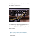


near the 10-pin connector (hite) running across
the top right corner of the controller.
From left to right, the X-Ais Limit Sitch black-and-
ello tisted ires should be plugged in rst,
folloed b the Y-Ais Limit Sitch ires, and then
the Z-Ais Limit Sitch ires. Four metal posts ill
remain as shon in the image belo.
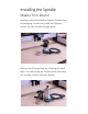
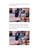
Connecting the Stepper
Motors
The motor etension ires hae connectors that
are polaried and can onl be connected properl
hen inserted as shon in the aboe image.
Each port is labeled along the bottom of the
Controller Board. The labels are directl beneath
each of the four ports.