Operating & Maintenance Instructions Asphalt Binder Analyser - Model ABA 7/35B This manual is for the guidance of operators of the above Carbolite product and must be read before the equipment is connected to the electricity supply. This manual should supply all the information required for safe and trouble-free operation. If, however, any questions remain unanswered please contact our Service Department at the address at the end of this manual.
Contents 2 1 Symbols & Warnings 3 2 Supplied Item List 4 3 ABA Installation 7 3.7.
1 Symbols & Warnings 1.1 Switches and Lights Instrument switch: when the instrument switch is operated the temperature control circuit is energised. Heat Light: the adjacent light glows or flashes to indicate that power is being supplied to the elements 1.2 Warning Symbols DANGER of electrical shock– read any warning printed by this symbol. DANGER – hot surface. Read any warning printed by this symbol. WARNING: all surfaces of a furnace may be hot. DANGER – read any warning printed by this symbol.
2 Supplied Item List 2.1 Parts Supplied The following items should be present. These should all be checked and identified as soon as possible after receipt of the equipment. The next page shows pictures of many of the parts for identification purposes. 2.1.
2.2 Identifying the Parts 2.2.1 Fig – Balance pan extension 2.2.2 Fig - Sample baskets on catch tray with lids & clips 2.2.3 Fig - Sample basket loading handle 2.2.4 Fig – Hot sample safety guard (assembled) 2.2.5 Fig – Hot sample safety guard handle fixing kit 2.2.7 5 Fig – Front brick cover 2.2.6 Fig – Safety warning label for hot sample safety guard 2.2.8 Fig – Calibration plate MF60 – 1.
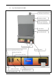
2.2.9 6 Fig – Functional parts of the ABA MF60 – 1.
3 ABA Installation 3.1 Tools Required 10mm spanner, 12mm spanner, cross point screwdriver, flat blade screwdriver, allen key (supplied), 5kg calibration mass (not supplied). 3.2 Unpacking Handling and Siting When unpacking and moving the ABA always lift it by its base; never lift it by the door or any other protruding part. The ABA weighs approximately120 kg please ensure that suitable equipment and an adequate number of personnel are available to safely lift the device into position.
3.3 Fitting the Chimney Remove the chimney panel, (see Fig 3.3.2) Fasten the chimney to the top of the ABA using the screws provided,( see Fig 3.3.3) Replace the chimney panel, (see Fig - 3.3.2) 3.3.1 Fig - Fastening the Chimney 3.3.3 3.3.2 Fig - Replacing the panel Fig – Chimney screws 3.4 Ducting The chimney must either be placed under a powered exhaust hood, or connected directly to a 76mm duct (not supplied) to the outside of the building; any such duct must NOT have powered extraction.
3.4.1 Fig - Ducting schematic 3.5 Hot Sample Guard Assembly The hot sample safety guard is supplied as a kit comprising the guard, the handles and fixing screws and a warning label and fixing screws. See Fig - 2.2.4 to Fig - 2.2.6. to assemble the handles and the warning label to the guard. 3.6 Electrical Connections Connection by a qualified electrician is recommended. Model ABA 7/35B is designed for connection to a range of power supplies with the minimum of circuit modifications.
of the operator. A line plug should be easily removable and should be within reach of the operator. The supply MUST incorporate an earth (ground). 3.6.1 Schematic for Mains Electrical Connections Failure to wire to the appropriate diagram may damage the ABA 10 MF60 – 1.
3.7 Balance Installation Remove the balance from its packing and isolate the ABA from the electrical supply. Remove both lower side covers. Open the chamber door and make sure that there are no obstructions, such as loose packing or insulation material, in the four holes in the chamber hearth that the legs of the balance pan extension pass through. 3.7.1 Fig - Positioning the Front Brick Cover Position the front brick cover over the front (see Fig 3.7.1).
3.7.6 Fig – Insert the balance through the left side of the furnace with the rear of the balance towards the front of the furnace 3.7.7 Fig -Using a spanner adjust the legs on the balance until the indicator on the bubble arm shows that it is level 3.7.8 Fig – Inserting the balance pan extension 3.7.9 3.7.10 Fig - Fastening the balance pan extension 12 3.7.11 Fig – Balance pan extension in place Fig - Allen key and screws MF60 – 1.
Open the door lock with the key provided. 3.7.12 Fig – Checking that the balance pan legs are central Insert the balance pan extension into the main chamber with the extension legs fitting through the four holes in the chamber hearth (Fig- 3.7.8 to 3.7.9). Note that the front edge of the extension is folded down. Fasten the balance pan extension to the balance using the four screws and Allen key supplied (see Fig- 0 to 3.7.11).
3.8 Installing Printer Paper The printer is located on the right hand side of the control panel. Access to the printer for changing the paper is provided by a hinged front panel. Depress the spring catch on the left hand side of the printer to release the front panel. The paper roll carrier is mounted on the rear of the printer front panel and will swing out from the main body for ease of printer paper roll changing (Fig 3.8.2) squeeze the spindle pins to release the roll and its retaining disc.
4 Safety Features In this section the word ‘user’ is to be interpreted as any person with access to or responsibility for the ABA 7/35B and its ancillary equipment. 4.1 Electric Shock Risk Lamps Opening the chamber door causes power to the heating elements to be disconnected at both ends of the circuit. Any failure of the relays involved in this switching causes one or two red Electric Shock Risk lamps to illuminate; see section 5.1 and section 5.2.
4.4 Door Lock Indication ‘Lamps’ on Touchscreen 4.4.1 Screen-view - Top status bar A ‘door locked lamp’ is shown on the top status bar on the user interface. If the door is locked then it is illuminated in orange, otherwise it is grey. The user should always check that the ‘door locked lamp’ is lit when a test is started. 4.
5 ABA Operation This section describes how to heat the chamber up to temperature, and how the automatic door locking system operates. 5.1 Switches – Control Panel The main control switches are on the left hand side of the control panel (see Fig 5.1.1). 5.1.1 Fig - Mains switch panel furnace power switch after burner heater lamp printer on/off switch USB data port safety circuit test switch main chamber heater lamps 5.1.
When the door is open power to the main chamber elements are automatically cut off. If a fault occurs then one or both of the red warning lamps above the door on the left (see Fig 5.1.2) will light up. These warning lamps should be tested daily by pressing the test switch on the lower mains switch panel (see Fig 5.1.1) when the door is closed and no test is running. The door open warning indicator in the header bar of the main menu screen (Screen-View 5.2.
5.3 General Operating Notes Heating element life is shortened by use at temperatures close to maximum. Do not leave the ABA at high temperatures when not required. The maximum temperature for the main chamber is 750°C (1380°F) and is factory set for the after burner at 900°C (1652°F) The chimney and should always be correctly fitted and unobstructed (see Fig 3.4.1) See section 20 for information about maintenance 5.
5.5 Touchscreen - Main Menu The main menu is accessed directly from the button in the top left corner of the home screen as shown in Fig 7.2.1. Table: 5.5.2 gives a reference to a section of this document where detailed information is given for each of the buttons on the Main Menu. 5.5.1 Screen-view: Main Menu 5.5.
6 System Configuration Menu Screen-view: 6.1.1 shows the System Configuration Menu which is accessed via: Home Screen → Main Menu → System Configuration Table: 6.1.2 gives a reference to a section of this document where detailed information is given for each of the buttons on the Configuration Menu. 6.1.1 Screen-view: System Configuration Menu 6.1.
7 Running a Test 7.1 Setup Before running the test for the first time, ensure the tray lift calculation has been performed as described in section 8. Before every test, the weights of the sample tray and sample must be determined as described in section 7.13. 7.2 Selecting a Recipe To start a test a recipe must first be created and then selected. Refer to section 14.1 for details on creating a recipe. To select a recipe go to the Recipe Library by pressing the ‘View Recipe Library’ button on the Main Menu.
7.3 Pre Test Requirements When the ‘Run Test’ button is pressed the controller will make several checks on the state of the system, which must pass, before the controller will allow the test to start. The checks and errors that are reported if a check fails are listed in Table: 7.3.1. 7.3.
7.4.2 Screen-view: In-test Display During a test the controller will continuously update the values circled in green, shown Screen-view: 7.4.2 . The values circled in red are updated every 30 seconds after the initial delay time + constant weight time has elapsed. For example, if the initial delay time is set to 10 minutes in the recipe and constant weight time is set to 3 minutes, then the values will be updated after 13 minutes and then every 30 seconds until the end of the test.
7.5 Power Failure During Test The door remains locked after a power failure. The key switch can be used to override the lock, but this feature is not recommended because of danger to the operator. Note that when power returns the display shows a message to indicate the power was interrupted during a test, see screen view 7.5.1. The test will re-start automatically, once the control software has started. The test results should be discarded.
7.7 Cancelling a Test A test can be cancelled by pressing the ‘Cancel Test’ button, shown in the ‘In Test Display’ screen (see 7.4.2). A pass number must then be entered. The pass number should be communicated only to authorised operators: this is a safety feature because of the danger of opening the door part way through a test (the operator should know the danger: others may not). The password is fixed at 728. It is safe to cancel a test by this method if there is no sample in the chamber (e.g.
7.9 Connecting an Adam Equipment™ External Balance Automatic weight entry requires an external balance to be connected to the 9 way female D-type connector mounted at the rear of the furnace. To connect to an Adam Equipment™ balance, use a 9 way, null modem, female to male cable. The required pin connections are 2-3, 3-2, 5-5, all other pins are unused. The external balance type must be set to Adam Equipment in the General Settings screen, ref. section 7.12.
The balance settings are shown in Table 7.10.2 7.10.2 Table: Ohaus Balance Settings Auto Print Print Internal Numeric Data Units: Gram (g) Baud Rate Parity Data Bits Stop Bits Off Off Off On 9600 None 8 1 7.11 Connecting an Ohaus Explorer Pro™ External Balance This section refers to the Ohaus balance with a colour touch screen interface. The external balance type must be set to Ohaus Explorer™ in the General Settings screen, ref. section 7.12.
When the Enter Weights button is pressed, the controller will attempt to communicate with an external balance. If it successful then external balance status on the Weight Entry screen will read ‘Ready’. If it fails then ‘No reply to weight request’ will be displayed. To retry the connection, return to the Home screen and then press ‘Enter Weights’ again. If a successful connection is made then ‘Ready’ will be displayed. 7.
7.13.2 Screen-view: Successful Weight Entry 7.14 Weight Entry Error Checking There is some basic built in error checking in the weight entry processing for both manual and automatic entry methods. If the combined weight entered is less than or equal to the tray weight then the error shown in Screen-view: 7.14.1 pops up. 7.14.1 30 Screen-view: Weight Entry Error Message MF60 – 1.
8 Tray Lift Calculation 8.1.11 8.1.12 Screen-view: Tray Lift Correction – in progress Screen-view: Tray Lift Correction - complete The Lift correction screen (8.1.11) is accessed via: 31 MF60 – 1.
Home Screen → Main Menu → Calculate Tray Lift. The air flow through the chamber causes lifting of the sample tray and balance; the amount of lift should be measured after installation and should be checked from time to time. Load the chamber with an empty sample basket assembly and catch tray, after it has reached its normal running temperature (e.g. 500°C). Allow the baskets to heat up for 10 minutes. The main chamber temperature is displayed on the screen for convenience.
9.1.1 9.1.2 33 Screen-view: Access Level Screen Screen-view: Supervisor Pass Code Entry MF60 – 1.
Table 9.
10 Temperature Control 10.1 Main Chamber & After Burner 10.1.11 Screen-view Temperature Control Screen Temperature control of the Main Chamber and After Burner is made using two independent PID control algorithms. The status of the control can be viewed on the Temperature Control screen (Screen-view 10.1.11 ) which is accessed via: Home Screen → Main Menu → Temperature The temperature readings on the left of the screen show the current temperature of the chambers.
The constituent elements of the PID control are also shown on the screen as Proportional, Integral and Derivative. 10.2 Heater On / Off Control The heater power can be switched on or off at any time using the red and blue buttons on the right hand side of the screen. On system power up the on/off status of the heater power is determined by an ‘Initial Heater Setting’ which is located on the ‘General Settings’ screen, (see Screen-view :10.2.1).
10.2.2 11 Setting Date and Time The date and time setting screen, ref. Screen-view:11.1.1, is accessed via: Home Screen → Main Menu → System Configuration → Set Date Time To change a date or time element, press the relevant white box. This will open the number pad screen and the relevant number can be adjusted accordingly. 11.1.1 Screen-view: Date and Time Setting Screen 11.1.2 Screen-view: Date Time Number Pad 37 MF60 – 1.
12 Printer Settings The printer settings screen, ref. Screen-view 12.1.1, is accessed via: Home Screen → Main Menu → System Configuration → Print Settings If the printer is not powered or disconnected from the controller (internal wiring) then the Printer Ready LED will be coloured red, otherwise this LED will be green. Pressing the ‘Printer Test’ button causes the current date, time, temperatures and weight to be printed in English.
12.1.1 Screen-view : Printer Setting Screen 12.1.2 39 Screen-view: Recipe Setting for Print Output MF60 – 1.
13 Recipe Library Functions The Recipe Library screen, ref. Screen-view 13.1.1, is accessed via: Home Screen → Main Menu → View Recipe Library If the list of recipes is empty then a new recipe will need to be created. Refer to section 14 on creating a new recipe. When the list of recipes is greater than 10 a scroll bar will appear on the right hand edge of the screen, see Screen-view 13.1.1. To perform any of the four operations: copy, edit, delete or run, on a recipe, touch the recipe name.
Note; if a configuration type recipe is being copied, the name will automatically be preceded by the tilde ‘~’ character when it is displayed in the Library list. 13.2.1 Screen-view: Copy Recipe Alpha Key Pad 13.3 Edit Recipe To edit a recipe, first select it by touching on the name and then press the ‘Edit’ button. The recipe editor will be displayed and populated with the values from the selected recipe. Refer to section 14 for details on the recipe editor. 13.
14 Recipe Editor A recipe is used to control the system behavior during a test and allows for precise repeatability from one test to another. 14.1 Standard and Calibration Recipes The recipe editor is operates in two modes: Standard and Calibration. The items displayed on the recipe editor screen differ between the two modes and resultant recipe will result in different calculations being performed at the end of the test.
14.1.2 Screen-view: Calibration Recipe 14.2 Recipe Name The recipe name is entered by touching the white box below the ‘Recipe Name’ label. The controller displays the Alpha pad, which allows a name, consisting of up to twenty characters, to be entered. 14.3 Save Recipe The save button will save the recipe file to flash memory. If a recipe with the same name already exists then a warning dialog will be displayed asking the operator if they wish to overwrite or cancel, see Screen-view 14.3.1 14.3.
14.4 End Triggers The functions of the Min % Weight Change, Constant Mass Limit and Constant Weight Time are described in section 7.6 - End of Test Trigger. 14.5 Initial Delay Time The Initial Delay Time parameter is the time period, in minutes, from the start of the test to the point where the End of Test conditions are monitored. This prevents a false End of Test condition from being detected at the start of the test.
15 Test Log Viewer When a test is run the interim and final results are output to a test log file and the printer. Note: if the Print Format in the recipe is set to Final Result, only the final results will be saved to the test log file and sent to printer.
15.1.1 Screen-view: Test Log Viewer – File List 15.1.2 Screen-view: Test Log Viewer – File Contents 46 MF60 – 1.
16 USB Memory Stick Data Transfer 16.
The colours of the LEDs on the USB Data Transfer screen, for different actions, are shown in Table: 16.2.1. 16.2.1 Table: LED Colours Memory Stick Inserted No Yes Yes 16.2.2 48 File Transfer in Progress N/A No Yes Memory Stick Detected Grey Green Green LEDs and Colour Copy Files Safe to Remove Memory Stick Grey Grey Grey Green Red Red Screen-view: USB Data Transfer – Test / Event Log Tab MF60 – 1.
16.2.3 17 Internal Balance Commands The balance command screen is accessible via: Home Screen → Main Menu → Balance Menu The screen is shown in Screen-view 17.1.1. The balance commands are: Tare Calibrate Adjust Filter If the balance is operating normally, then the balance status will display ‘Ready’. If communication is lost between the balance and the controller, the balance status will display ‘No reply to setup command’ and the cable between the controller and balance should be checked. 17.1.
17.2 Tare Command Pressing the tare button will zero the balance by sending a tare command to the balance. The balance status will display ‘Tare started…’ then ‘Tare complete’, for about 2 seconds before displaying ‘Ready’ again. The weight reading should read zero grams. 17.3 Calibrate To calibrate the balance a 5 kg calibration mass is required. The balance must be calibrated after installation and if the equipment is moved it is also good working practice to check calibration periodically.
17.3.1 Screen-view Balance Control Screen - Calibration 17.4 Filter Setting The white number box, next to Filter Setting screen label, can be touched to change the balance filter setting. The controller will display the number pad and a value from 1 to 3 can be entered.
18 Language Selection The screen can display text in different languages, provided the relevant language translation files have been loaded onto the controller. Also the test results (ref. section 15) will be stored in the selected language. The language selection screen is accessed via: Home Screen → Main Menu → System Configuration → Language Setting The screen is shown in Screen-view: 18.1.1 with ‘English’ selected.
19 Reconfigure Voltage Settings For Alternative Electrical Supply Caution: Do not increase the power limit value to a value above the design level for the operating voltage as shown in the table below. In the default configuration a ‘Supervisor’ level security access is required. The power limit is a feature which is used to match the heating elements to the supply voltage. If the voltage is stated at the time of order, no adjustment is necessary.
20 Temperature Calibration After prolonged use the controller and/or thermocouple could require recalibration. This would be important for the process. A quick check using an independent thermocouple and temperature indicator should be made from time to time to determine whether full calibration is required. 20.1 Single Point Calibration 1 point calibration uses one offset value across the temperature range.
20.2 Dual Point Calibration Dual Point Calibration uses two offset values and creates a linear temperature slope between the two values. Home Screen → Main Menu → System Configuration → Temperature Calibration Select “Dual Point” Calibration In the “Low Temperature Point” box enter the lower temperature at which you want to apply your offset. In the “Offset” box enter the offset value for the low temperature point.
21 Maintenance and Repairs 21.1 Safety Note: Refractory Fibrous Insulation The ABA contains Insulation made from High Temperature Insulation Wool Refractory Ceramic Fibre, (better described as Alumino Silicate Wool) (ASW) This product contains alumino silicate wool products in its thermal insulation. These materials may be in the form of blanket or felt, formed board or shapes, mineral wool slab or loose fill wool.
21.3 Cleaning and Hours of Use Monitoring Soot can accumulate in the airway following the after-burner, giving rise to fire risk. There is a plenum chamber with removable panels to give access to cleaning; see section 21.4. The user is responsible for maintaining a clean plenum chamber, and also for regular cleaning of the chimney and the external flue or ducting system.
21.3.2 Screen-view: Cleaning Warning Message 21.4 Cleaning the Plenum Chamber and Fan Impeller Remove the upper side access panel, and the cover of the plenum chamber. (see section 4.3). Clean out all accumulated soot and debris using a vacuum cleaner. Also clean any accumulated soot from the fan impeller located at the back of the plenum chamber.
21.6 Recommended Spares Carbolite can supply individual spares, or a kit of the items most likely to be required. Please consult Carbolite Sales Department for details of recommended spares. 21.7 Temperature Controller Replacement Temperature control in both the main chamber and the after burner for this version of the ABA is managed by the central control unit. We would recommend that replacement of the central control unit is done by a Carbolite authorised engineer.
21.12 Catch Tray Straightening The stresses caused by repeated heating and cooling can cause the catch tray (Fig: 2.2.2) to distort, allowing the catch tray to rock in use, giving an unstable balance reading. The distortion takes the form of two opposite corners bending up and the other two opposite corners bending down. Straighten the tray by resting the two lower corners on supports, and pressing down on the higher corners. Repeat this operation until the tray is flat. 21.
21.26.1 61 Fig: Interface Layout MF60 – 1.
22 Event Log Messages Significant events that occur during operation are recorded with a time stamp in an event log text file, which is stored in flash memory on the controller. A new event log file is created every day the system is used. The file name has the following format: ABA_Event_Logyyyy-mm-dd.txt Where yyyy is the four digit year, mm is the two digit month and dd is the day of the month. E.g. ABA_Event_Log2011-03-24 The number of files held on the system is limited to 100.
An example of the log file contents is shown below: Note: some internal wiring was disconnected to deliberately create the I/O board communication errors. 09:40:37 Power up 09:49:10 Configuration access level set 09:50:44 Save recipe: overwriting existing recipe CARBOLITE1 09:51:02 Tare balance command 09:56:03 New weights entered: 09:56:03 Tray Weight = 214.3 09:56:03 Combined Weight = 272.9 09:56:03 Sample Weight = 58.
23 Software Versions There are three software applications that control different elements of the system: Balance Temperature Control Board Main Controller (including user interface) As the software for each of these elements can be changed independently, a software version number is reported for each one. These version numbers can be found via: Home Screen → Main Menu → Software Versions Image 23.1.1 shows the software versions screen.
24 Diagnostics There is a diagnostic screen which is accessible via: Home Screen → Main Menu → System Configuration → Diagnostics This screen is shown in Image 24.1.1. The screen allows manual override of the following controls: buzzer, door lock, fan and balance switch. Note: the balance switch is this case refers to a relay which switches the RS232 communication link between the internal and external balance.
25 Fault Finding Disconnect the equipment from the supply before carrying out any internal investigation.
Furnace Overheats (continued) ► The SSR has The Heat lamp/s remain failed ‘ON’ on when the controller is off ► No fault. Burning bitumen A temperature that is higher causes the temperature to than the increase above the set point. set-point is This is normal.
Warning Lamp & Door Faults (continued) ► The key has been used Door does not lock at start of and left in unlocked test position ► Door switch failure ► Interface board failure ► Loose connection lead Balance Errors Weight ► Balance not properly readings not installed.
26 Circuit Diagram and Fuses 69 MF60 – 1.
26.1 Fuses The following fuse types are present: Supply Fuses: 32mm x 6mm type F, 16A – 6 total (4 on board EMC filter units; 2 in separate holders). Auxiliary Fuses (on board EMC filter unit): 20mm x 5mm glass type F, 2A. 26.2 Customer Supply Fusing High break capacity fuses should be used. Avoid fast-blow fuses and magnetic trip circuit breakers - consult Carbolite if in doubt. The supply fuse rating should be as follows: Table 26.
27 Specifications 27.1 Representations Covered by this Manual Carbolite reserves the right to change specifications without notice. The Carbolite model ABA 7/35B, Asphalt Binder Analyser, designed and built to comply with BS/EN 12697-39:2004 and ASTM D6307-10, and AASHTO T308-10. Height without chimney Height with chimney Width Depth (length) Optional Stand Weight Power Rating 980 mm 1160 mm 600 mm 770 mm 600 mm high 120kg (approximate) 8000 Watts 27.
The products covered in this manual are only a small part of the wide range of ovens, chamber furnaces and tube furnaces manufactured by Carbolite for laboratory and industrial use. For further details of our standard or custom built products please contact us at the address below, or ask your nearest stockist. Parsons Lane Hope, Hope Valley S33 6RB England ISO 9001: 2008 Registered Company Tel: + 44 (0) 1433 624242 Fax: + 44 (0) 1433 624243 Email: service@carbolite.com Web: www.carbolite.