Operating & Maintenance Instructions “MTT 12/38/850” Combustion Tube Furnace for Carbon-14 & Tritium Analysis This manual covers the operation of the furnace only. See also the Process Manual. CONTENTS Section 1.0 2.0 3.0 4.0 5.0 6.0 7.0 8.0 9.
MTT 1.0 SYMBOLS & WARNINGS 1.1 Switches and Lights Instrument switch: when the instrument switch is operated the temperature control circuit is energised. Heat Switch: the switch disconnects power to the heating elements; unless this switch is off there is a danger of electric shock when inserting objects into the furnace Heat Light: the adjacent light glows or flashes to indicate that power is being supplied to the elements 1.
MTT 2.0 INSTALLATION 2.1 Unpacking & Handling When unpacking or moving the furnace always lift it by its base or by both ends of the main body. Never lift it by its work tube or the surrounding insulation. Use two people to carry the furnace. Remove any packing material before use. Place the furnace in a well ventilated room, away from other sources of heat, and on a surface which is resistant to accidental spillage of hot materials. Do not mount the furnace on an inflammable surface.
MTT 2.3 Connection to a Computer This furnace is normally fitted with RS485 3-wire communications on the main controller only. For information, RS232 and 5-wire connections are also shown below. This section does not apply if the digital communication facility is not fitted. If the RS232 option is supplied, then the furnace is fitted with one subminiature D-socket connected to the controller comms module.
MTT 3.0 OPERATION 3.1 “MTT 12/38/850” – two zone combustion tube furnace. The furnace is based on the Carbolite model MTF 12/38/400, but has two independent zones, giving twice the heated length in total. The two zones are wound on a single ceramic tube (38/46 x 900mm long); each zone is approximately 400mm length. The zones are separated by approximately 10mm because of the requirement for separate overtemperature systems. The extended control box type CBT is used for the base.
MTT 3.3 General Operating Advice Heating element life is shortened by use at temperatures close to maximum. Do not leave the furnace at high temperature when not required. The maximum temperature is shown on the furnace rating label and on the back page of this manual. Switch off the Heater switch whenever loading or unloading anything into the ceramic worktube see the safety warning below. Lightweight ceramic fibre insulation can easily be marked by accidental contact.
MTT 4.0 MAINTENANCE 4.1 General Maintenance No routine maintenance is required. The outer surfaces may be cleaned with a damp cloth. Do not allow water to enter the interior of the case, tube or control box. Do not clean with organic solvents. 4.2 Calibration After prolonged use the controller and/or thermocouple could require recalibration. This would be important for processes which require accurate temperature readings or which use the furnace close to its maximum temperature.
MTT 5.0 REPAIRS & REPLACEMENTS 5.1 Safety Warning – Disconnection from Supply Always ensure that the furnace is disconnected from the supply before repair work is carried out. 5.2 Safety Warning - Refractory Fibrous Insulation Insulation made from High Temperature Insulation Wool Refractory Ceramic Fibre, (better described as Alumino Silicate Wool) (ASW) This product contains alumino silicate wool products in its thermal insulation.
MTT 5.5 Thermocouple Replacement Disconnect the furnace from the supply. It is necessary to separate the furnace from its base or stand. Remove the back panel of the control base and remove the bolts which hold the furnace terminal cover to the base. Remove the self-tapping screws which hold the terminal cover to the cylindrical furnace body. Make a note of the thermocouple connections. The negative leg of the thermocouple is marked blue.
MTT Let the furnace heat up at its maximum rate to 900°C without interruption, and then soak for 1 hour. Fumes may be emitted: this should be done in conditions of good ventilation. Check that the furnace is controlling properly to rule out the possibility that the element failed because of a fault in the control system. If you have any problems with this procedure, please contact our service division. 5.7 Fuse Replacement Fuses are marked on the circuit diagram (section 7.0) with type codes, e.g. F1, F2.
MTT 6.0 FAULT ANALYSIS A. Furnace Does Not Heat Up 1. The HEAT light The heating element has failed is ON 2. The HEAT light is OFF Check also that the SSR is working correctly The controller shows a very high temperature or a code such as S.
MTT 7.0 CIRCUIT DIAGRAMS MTT – Single Phase 7.1 N L F1 EMC Filter heater switch F2 PE Instrument Switch coil overtemp. controller heat thermocouple SSR temperature controller element thermocouple coil overtemp. controller heat thermocouple SSR temperature controller element thermocouple 12 MF38 – 3.
MTT 8.0 FUSES & POWER SETTINGS 8.1 Fuses Supply fuses (F1 in circuit diagram) - 12.5A glass type F 32mm x 6mm Control circuit fuses (F2 in circuit diagram) - 5A glass type F 20mm x 5mm Note: the internal supply fuses are rate at 12.5A although the maximum power of the furnace is rated at 13A. Because of power control the 12.5A fuses should be adequate. Should these fuses blow, then 16A may be substituted. Should 16A fuses blow, there is a circuit fault.
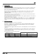
MTT 9.0 SPECIFICATIONS Carbolite reserves the right to change specifications without notice. 9.1 Models Covered by this Manual MODEL Max. Temp. Max. Power Work Work Heated Uniform Tube Tube Length Zone 1 Bore Length Length (°C) (kW) (mm) (mm) (mm) (mm) Special combustion tube furnace for Carbon-14 & Tritium analysis. Two-zone tube furnace with a ceramic work tube wound with resistance wire.
MTT MF38 – 3.
The products covered in this manual are only a small part of the wide range of ovens, chamber furnaces and tube furnaces manufactured by Carbolite for laboratory and industrial use. For further details of our standard or custom built products please contact us at the address below, or ask your nearest stockist.