Installation, Operation & Maintenance Instructions 1200°C Split Tube furnaces types HST & VST This manual is for the guidance of operators of the above Carbolite products and should be read before the furnace is connected to the electricity supply. CONTENTS Section 1.0 2.0 3.0 4.0 5.0 6.0 7.0 8.0 9.
HST, VST INTRODUCTION 1.1 VST & HST models The VST range comprises split tube furnaces designed for use vertically, with several mounting options: the furnace may be provided with no stand; or with a wall bracket; or it may be fitted to one of two stand designs – near and far. The HST range uses the same insulated split case as the VST, fitted inside an outer case designed for horizontal use – though this may be fitted to an L-stand which allows for both horizontal and vertical use.
HST, VST INSTALLATION 2.1 Unpacking & Handling When unpacking or moving the furnace always lift it by its case or main body. Never lift it by its insulation or by a fitted work tube. If possible use two people to carry the furnace and remote control box. Remove any packing material from inside the furnace before use. If an optional or special stand is separately supplied, assemble the furnace on to it.
HST, VST 2.4 Electrical Connections Connection by a qualified electrician is recommended. The furnaces covered by this manual normally require a single phase A.C. supply, which may be Live to Neutral non-reversible, Live to Neutral reversible or Live to Live. Some models may be ordered for 3-phase use (and if so, are “universal” – see section 2.5). Check the furnace rating label before connection.
HST, VST OPERATION The instructions for operating the temperature controller are given in a separate manual. If the furnace is fitted with a time switch, see also the supplementary manual MS03. If cascade control is fitted, see the supplementary manual MS07. 3.1 Operating Cycle The furnace is fitted with a combined Supply light and Instrument switch. The light is on whenever the furnace is connected to the supply. The switch cuts off power to the control circuit.
HST, VST Do not set too high a heating rate. Large diameter tubes are more susceptible to thermal shock than smaller. Tubes which extend beyond the heated part of the furnace are more at risk. A general rule for maximum heating rate is 400/internal diameter (°C/min); for 75mm i/d tubes this comes to 5°C per minute. The controller can be set to limit the heating rate. 3.5 Pressure Work tubes are not able to accept high internal pressure.
HST, VST MAINTENANCE 4.1 General Maintenance No routine maintenance is required. The outer surfaces may be cleaned with a damp cloth. Do not allow water to enter the case, chamber or control box. Do not clean with organic solvents. 4.2 Calibration After prolonged use the controller and/or thermocouple could require recalibration. This would be important for processes which require accurate temperature readings or which use the furnace close to its maximum temperature.
HST, VST REPAIRS & REPLACEMENTS 5.1 Safety Warning – Disconnection from Supply Always ensure that the furnace is disconnected from the supply before repair work is carried out. 5.2 Safety Warning - Refractory Fibrous Insulation This furnace contains refractory fibres in its thermal insulation. These materials may be in the form of fibre blanket or felt, vacuum formed board or shapes, mineral wool slab or loose fill fibre.
HST, VST 5.5 Thermocouple Replacement The coverings and guards which must be removed to gain access to the thermocouple depend on the model, and any mounting options or fittings. Study the furnace layout and consult Carbolite if in doubt. Disconnect the furnace from the supply, and remove covers and guards as necessary. Make a note of the thermocouple connections. The negative leg of the thermocouple is marked blue.
HST, VST Element Replacement Please see safety note 5.2 - please wear a face mask. HST, and VST with far hinge: Remove the three screws from each end and lift out the half-circular insulation assembly. Make a plan of all the cable connections and disconnect the cables. Remove the thermocouple(s) by withdrawing them from the sheaths built into the elements. Remove the plates through which the element tails are located. Remove the keep plates from each side of the insulation assembly.
HST, VST FAULT ANALYSIS A. Furnace Does Not Heat Up 1. The HEAT light Æ The heating element has failed is ON Æ Check also that the SSR is working correctly 2. The controller shows a very high temperature or a code such as S.
HST, VST CIRCUIT DIAGRAMS Safety Switches type A: a 2-pole Heater Switch is fitted directly in the element circuit in models up to 16A rating. Two “door switches” are also fitted in the element circuit up to 25A rating. Safety Switch type B: a Heater Switch is fitted into the contactor coil circuit in models over 16A. A door switch is fitted into the contactor coil circuit over 25A rating. Single Phase 7.
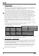
HST, VST 7.4 3-phase without neutral (delta) Filter (if fitted) L3 L2 L1 F1 contactor F2 PE F3 Supply light & Instrument Switch heat on coil safety switch overtemp. controller if fitted thermocouple temperature controller F3 heat on F3 e l e m e n t (s) heat on e l e m e n t (s) F3 SSR F3 SSR thermocouple 7.5 e l e m e n t (s) F3 SSR 3-phase without neutral (star – e.g.
HST, VST 7.7 3-phase “universal” wiring Filters (if fitted) N L N L N L F1 F2 F3 Supply light & Instrument Switch safety switch overtemp. controller temperature controller Contactors (2 or 3) coil heat on coil if fitted thermocouple e l e m e n t (s) F3 heat on e l e m e n t (s) F3 heat on e l e m e n t (s) F3 SSR F3 SSR thermocouple F3 SSR Fuses F1 are always present in this wiring design. Fuses F2 could be absent in some circumstances, if the circuit does not exceed 10A.
HST, VST FUSES & POWER SETTINGS 8.1 Fuses F1-F3: Refer to the circuit diagrams. F1 F2 F3 Fitted if supply cable fitted. Fitted on board to some types of EMC filter. Internal supply fuses Auxiliary circuit fuses Fitted on board to some types of EMC filter. May be omitted up to 25Amp/phase supply rating. Heat Light fuses May be omitted up to 25 Amp/phase supply rating. Customer fuses Required if no supply cable fitted. Recommended if cable fitted.
9.0 MF13 – 3.
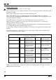
SPECIFICATIONS Carbolite reserves the right to change specifications without notice. 9.1 Models Covered by this Manual Heated Net 1 Work Work Length Weight Tube Tube Length Bore (°C) (kW) (mm) (mm) (mm) (kg) Split Tube furnaces heated by resistance wire moulded in refractory fibre Horizontal Models in an opening case HST 12/--/200 1200°C 1.0 25-100 350200 26 HST 12/--/300 1200°C 1.5 25-100 450400 29 HST 12/--/400 1200°C 2.0 25-100 550400 32 HST 12/--/500 1200°C 2.0 25-100 550400 37 HST 12/--/600 1200°C 3.