Cybex 770A/770AT Arc Trainer® Owner’s Manual Cardiovascular Systems Part Number 5770-4 C www.cybexintl.
Cybex Owner’s Manual Table of Contents FCC Compliance Information . . . . . . . . . . . . . 3 E3 View Monitor Screen Options . . . . . . . . . . Heart Rate Indicator . . . . . . . . . . . . . . . . . . . Fan Control . . . . . . . . . . . . . . . . . . . . . . . . . . iPod Functions . . . . . . . . . . . . . . . . . . . . . . . . Safety Ground and Voltage Information . . . . . . . . . . . Important Safety Instructions . . . . . . . . . . . . . . Warnings and Cautions . . . . . . . . . . . . . . . . . .
Cybex Owner’s Manual FCC Compliance Information Changes or modifications to this unit not expressly approved by the party responsible for compliance could void the user’s authority to operate the equipment! This equipment has been tested and found to comply with the limits for a Class B digital device, pursuant to part 15 of the FCC Rules. These limits are designed to provide reasonable protection against harmful interference in a residential installation.
Cybex Owner’s Manual Safety Read all instructions and warnings before using. Ground and Voltage Information DANGER: Death or serious injury can occur. To avoid death or serious injury the following precautions must be observed. Equipment must be properly grounded. Check with a qualified electrician or service provider to verify the unit is properly grounded. Improper connection of equipment grounding can result in electric shock. For E3 View Monitor or Optional Power Supply • Unit must be grounded.
Cybex Owner’s Manual Important Safety Instructions (Save These Instructions) DANGER: Death or serious injury can occur. To avoid death or injury the following procedure must be followed. Always unplug this unit from the electrical outlet before cleaning. Unplugging equipment reduces risk for shock. User Safety Precautions • • • • • • • • • • • • • KEEP ALL CHILDREN 12 AND UNDER AWAY! Teenagers or disabled must be supervised. Obtain a medical exam before beginning any exercise program.
Cybex Owner’s Manual • • • • • • Do not attempt electrical or mechanical repairs. Seek qualified repair personnel when servicing. If you live in the USA, contact Cybex Customer Service at 888-462-9239. If you live outside the USA, contact Cybex Customer Service at 508-533-4300. Use only Cybex supplied components to maintain/repair unit. Keep a repair log of all maintenance activities. Disconnect the optional power adapter before servicing unit.
Cybex Owner’s Manual • • • • • • • • • • • • Do not defeat the safety purpose of the polarized or grounding-type plug. A polarized plug has two blades with one wider than the other. A grounding type plug has two blades and a third grounding prong. The wide blade or the third prong is provided for safety. If the provided plug does not fit into outlet, consult an electrician for replacement of the obsolete outlet.
Cybex Owner’s Manual Warnings and Cautions To replace any worn or damaged decals do one of the following: Visit www.cybexintl.com to shop for parts online, fax orders to 508-533-5183 or contact Cybex Customer Service at 888-462-9239. If you are located outside of the USA, call 508-533-4300. For location or part number of labels, see the parts list and exploded-view diagram on the Cybex web site at www.cybexintl.com.
Cybex Owner’s Manual Label Placement 770A-331-4 770A-332-4 1.80 1.25 R .12 4 PLACES CAUTION Moving parts. Keep hands away when in use. CAUTION SAFETY YELLOW PMS 108 BACKGROUND BLACK TRIANGLE W/ YELLOW EXCLAMATION POINT, BLACK LETTERS 18.9 PT ARIAL BLACK FONT Moving parts. Keep hands away when in use. DE-17219-4 B DE-17219-4 B PART NUMBER 6.
Cybex Owner’s Manual Assembly Specifications - 770A Classification Accuracy Length Width Height: Weight of Product Shipping Weight Incline Levels Resistance Levels Stride Length S (Studio) A 76.25” (194 cm) 32” (81 cm) 62.5” (159 cm) 404 lbs (183 kg) 429 lbs (195 kg) 0-20 0-100 24” (61 cm) fixed length. Quick Start, five workout groups, seven workouts, three heart rate workouts, and Workouts two power workouts Upper console: LED or E3 View Monitor.
Cybex Owner’s Manual Specifications - 770AT Classification Accuracy Length Width Height: Weight of Product Shipping Weight Incline Levels Resistance Levels Stride Length S (Studio) A 76.25” (194 cm) 36.28” (92 cm) 62.5”(159 cm) 412 lbs. (187 kg.) 437 lbs. (198 kg.) 0-20 0-100 24” (61 cm) fixed length. Quick Start, five workout groups, seven workouts, three heart rate workouts, and Workouts two power workouts Upper console: LED or E3 View Monitor.
Cybex Owner’s Manual Environment and Storage Humidity and Static Electricity The unit is designed to function normally in an environment with a relative humidity range of 30% to 75%. The unit can be shipped and stored in a relative humidity range of 10% to 90%. Dry air may cause static electricity. During workout, user may experience a shock due to build-up of static electricity on the body and the discharge path of the unit.
Cybex Owner’s Manual 770A Assembly Procedure Tools Required • • • • • Phillips screwdriver Stubby Phillips screwdriver 3/16” Allen wrench (supplied) 7/32” Allen wrench (supplied) 9/16” Open end wrench (2) The words “left” and “right” denote the user’s orientation. Two people will be required for this procedure. Read and understand all instructions thoroughly before assembling this unit. Check all items carefully.
Cybex Owner’s Manual #20 #21 #22 #23 #15 #9 #16 #17 #18 #10 #11 #7 #19 #12 #13 #6 #14 #8 #2 #3 #24 #1 #25 #4 14 #5
Cybex Owner’s Manual Verify contents of hardware pack See hardware pack listings and hardware pack contents. See Customer Service for contact information if any parts are missing. Item 26 27 28 29 30 31 32 33 Quantity 1 4 1 4 4 6 19 8 Part Number BK030204 HC700430 HF540200 HN704901 HT592526 HT532512 HT552512 HT572515 Description 7/32” Allen Wrench BHSCS .375-16 x 2.50” Grommet, Nylon Locknut, .375-16 Nylon Tap Sc 10-12 x 2.00 Pn Hd Phil Screw, Pan Head Phillips, #6 x .
Cybex Owner’s Manual #2 #7 #6 #8 #29 #28 #33 #31 #1 #30 #4 #32 #16 #15 #33 #32 #17 #27 #24 #33 #18 #31 #10 #5 #9 #32 #32 #13 #11 #32 #32 #12 #33 #32 #33 #14 #3 16
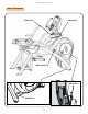
Cybex Owner’s Manual Lift and move unit 1. Remove large bolts and shipping supports. Keep package material on linkage arms at this time. This will protect the paint from scratching during assembly. 2. Grasp each rear support leg firmly and lift with one person on each side. 3. Lift the lower rear support legs using proper lifting methods so the front transport wheels are able to roll on floor. 4. Move unit to intended location. 5. Lower rear support legs. Attach 770A console assembly. 1.
Cybex Owner’s Manual Install coax cable (E3 View Monitor option) 1. Remove four screws securing back cover to the console using a Phillips screwdriver. Back Cover Screws (4) 2. Route coax cable up through console support tube. Console Support Tube Coax Cable E3 View Monitor Coax Connection 3. Install coax cable into the E3 View Monitor coax connector and tighten threaded connector. 4. Install four screws securing back cover to console using a Phillips screwdriver.
Cybex Owner’s Manual Install accessory tray base 1. Place the accessory tray in position on the frame and route the iPod cable towards the back of the unit. Do not pinch optional coax cable. Accessory Tray Base iPod Cable Coax Cable (E3 View Monitor option) Frame Screws (4) 2. Install the four screws using a stubby Phillips screwdriver. Install accessory tray top 1. Place the accessory tray top in position on the accessory tray base and route the iPod cable through the notch in the accessory tray.
Cybex Owner’s Manual Install accessory tray bottom Install the grommet to the frame. Frame Grommet Install the accessory tray bottom to the accessory tray base with three screws using a Phillips screwdriver.
Cybex Owner’s Manual Install handrails. 1. Remove three locknuts from the left support leg using two 9/16” open end wrenches. Keep the two spacers in place. Left Handle Locknuts (3) Spacers (2) 2. Install the left handle and three locknuts using two 9/16” open end wrenches. 3. Install the left inner rear cover with two screws using a Phillips screwdriver.
Cybex Owner’s Manual 4. Install the left outer rear cover with five screws using a Phillips screwdriver. Screws (2) Left Outer Rear Cover Screws (3) 5. Install the left top rear cover with five screws using a Phillips screwdriver. Screws (5) Left Top Rear Cover 6. Install the left inner and outer collars with two screws using a Phillips screwdriver. Collars are marked with an “L” on the inside and have a left and right side.
Cybex Owner’s Manual 7. Remove three locknuts from the right support leg using two 9/16” open end wrenches. Keep the two spacers in place. Right Handle Locknuts (3) Spacers (2) 8. Install the right handle and three locknuts using two 9/16” open end wrenches. 9. Install the right inner rear cover with two screws using a Phillips screwdriver.
Cybex Owner’s Manual 10. Install the right outer rear cover with five screws using a Phillips screwdriver. Screws (2) Screws (3) Right Outer Rear Cover 11. Install the right top rear cover with five screws using a Phillips screwdriver. Right Top Rear Cover Screws (5) 12. Install the right inner and outer collars with two screws using a Phillips screwdriver. Collars are marked with an “R” on the inside and have a left and right side.
Cybex Owner’s Manual Attach foot pads Have one person lift the unit while a second person places a foot pad under each of the two back feet. Foot Pads (2) Level unit onfirm unit is on a level surface. If not, use a 9/16” open-end wrench to adjust the leveling feet up or C down. Leveling Feet Install coax cable (E3 View Monitor option) Install 6’ coax cable to the coax cable connector in base of unit.
Cybex Owner’s Manual Visually inspect unit 1. Carefully remove any package material from arms and rest of unit. 2. Carefully examine the unit to ensure assembly is correct and complete. 770AT Assembly Procedure Tools Required • • • • • Phillips screwdriver Stubby Phillips screwdriver 3/16” Allen wrench (supplied) 7/32” Allen wrench (2) (supplied) 9/16” Open end wrench (2) The words “left” and “right” denote the user’s orientation. Two people will be required for this procedure.
Cybex Owner’s Manual Item 22 23 24 #20 Quantity 1 1 1 #21 #22 Part Number 770A-415 770A-416 770A-427 Description Commercial Arc warranty sheet Consumer Arc warranty sheet Cable, 6’, Coax (E3 View Monitor option) #23 #9 #15 #16 #17 #10 #11 #7 #19 #18 #12 #6 #13 #14 #8 #2 #3 #1 #24 #4 27 #5
Cybex Owner’s Manual Verify contents of hardware pack See hardware pack listings and hardware pack contents. See Customer Service for contact information if any parts are missing. Item 25 26 27 28 29 30 31 32 33 34 35 36 37 38 Quantity 2 1 2 4 1 4 4 2 6 19 8 2 3 1 Part Number 600A-311 BK030201 BK030204 HC700428 HF540200 HN704901 HT592526 HS307601 HT532512 HT552512 HT572515 HX622815 PL-16535 YA000201 Description Flange Spacer 3/16” Allen Wrench 7/32” Allen Wrench BHSCS .375-16 x 2.
Cybex Owner’s Manual #2 #7 #6 #8 #30 #35 #33 #1 #16 #31 #17 #4 #34 #15 #35 #28 #29 #35 #33 #18 #37 #25 #10 #32 #9 #35 #36 #38 #5 #13 #34 #11 #34 #34 #12 #35 #34 #35 #14 #3 29 #34
Cybex Owner’s Manual Lift and move unit 1. Remove large bolts and shipping supports. Keep package material on linkage arms at this time. This will protect the paint from scratching during assembly. 2. Grasp each rear support leg firmly and lift with one person on each side. 3. Lift the lower rear support legs using proper lifting methods so the front transport wheels are able to roll on floor. 4. Move unit to intended location. 5. Lower rear support legs. Attach 770AT console assembly. 1.
Cybex Owner’s Manual Install coax cable (E3 View Monitor option) 1. Remove four screws securing back cover to the console using a Phillips screwdriver. Back Cover Screws (4) 2. Route coax cable up through console support tube. Console Support Tube Coax Cable E3 View Monitor Coax Connection 3. Install coax cable into the E3 View Monitor coax connector and tighten threaded connector. 4. Install four screws securing back cover to console using a Phillips screwdriver.
Cybex Owner’s Manual Install accessory tray base 1. Place the accessory tray in position on the frame and route the iPod cable towards the back of the unit. Accessory Tray Base iPod Cable Coax Cable (E3 View Monitor option) Frame Screws (4) 2. Install the four screws using a Phillips screwdriver. Install accessory tray top 1. Place the accessory tray top in position on the accessory tray base and route the iPod cable through the notch in the accessory tray.
Cybex Owner’s Manual Install accessory tray bottom Install the grommet to the frame. Frame Grommet Install the accessory tray bottom to the accessory tray base with three screws using a Phillips screwdriver.
Cybex Owner’s Manual Install handrails. 1. Remove three locknuts from the left support leg using two 9/16” open end wrenches. Keep the two spacers in place. Left Handle Locknuts (3) Spacers (2) 2. Install the left handle and three locknuts using two 9/16” open end wrenches. 3. Install the left inner rear cover with two screws using a Phillips screwdriver.
Cybex Owner’s Manual 4. Install the left outer rear cover with five screws using a Phillips screwdriver. Screws (2) Left Outer Rear Cover Screws (3) 5. Install the left top rear cover with five screws using a Phillips screwdriver. Left Top Rear Cover Screws (5) 6. Install the left inner and outer collars with two screws using a Phillips screwdriver. Collars are marked with an “L” on the inside and have a left and right side.
Cybex Owner’s Manual 7. Remove three locknuts from the right support leg using two 9/16” open end wrenches. Keep the two spacers in place. Right Handle Locknuts (3) Spacers (2) 8. Install the right handle and three locknuts using two 9/16” open end wrenches. 9. Install the right inner rear cover with two screws using a Phillips screwdriver.
Cybex Owner’s Manual 10. Install the right outer rear cover with five screws using a Phillips screwdriver. Screws (3) Right Outer Rear Cover Screws (3) 11. Install the right top rear cover with five screws using a Phillips screwdriver. Right Top Rear Cover Screws (5) 12. Install the right inner and outer collars with two screws using a Phillips screwdriver. Collars are marked with an “R” on the inside and have a left and right side.
Cybex Owner’s Manual Remove left and right handle assembly The left and right handle assemblies are shipped in rotated positions. The handle assemblies must be removed and rotated 180 degrees for proper setup and assembly. Shipping Position 1. Remove a screw and washer from the left handle assembly using two 7/32” Allen wrenches. Screw Washer Left Handle Pivot Pin Assembly 2. Slide pivot pin assembly out and remove left handle assembly. 3. Rotate left handle assembly 180 degrees. 4.
Cybex Owner’s Manual 7. Remove a screw and washer from the right handle assembly using two 7/32” Allen wrenches. Screw Washer Right Handle Pivot Pin Assembly 8. Slide pivot pin assembly out and remove right handle assembly. 9. Rotate right handle assembly 180 degrees. 10. Apply Loctite to threads inside the pivot pin and screw. 11. Place right handle assembly in position and slide pivot pin assembly back in place. 12.
Cybex Owner’s Manual Install right linkage rod 1. Pivot right handle assembly up and slide right linkage rod onto right arm. Flange Spacer Right Linkage Rod Linkage Rod Cap Washer Loctite Screw Right Arm 2. Place a drop of Loctite onto the screw. 3. Install the screw, washer, linkage rod cap, and flange spacer using a 3/16” Allen wrench. 4. Tighten screw to a minimum of 90 in/lbs. Verify handle assemblies are now installed in the correct position.
Cybex Owner’s Manual Connect contact heart rate cable 1. Plug right heart rate cable into main frame socket. Right Side Shown Main Frame Socket Heart Rate Wire Position plug so handle does not rub cable during operation. 2. Plug left heart rate cable into main frame socket. Attach foot pads Have one person lift the unit while a second person places a foot pad under each of the two back feet.
Cybex Owner’s Manual Level unit onfirm unit is on a level surface. If not, use a 9/16” open-end wrench to adjust the leveling feet up or C down. Leveling Feet Install coax cable (E3 View Monitor option) Install 6’ coax cable to the coax cable connector in base of unit. 6’ Coax Cable Coax Cable Connector Visually inspect unit 1. Carefully remove any package material from arms and rest of unit. 2. Carefully examine the unit to ensure assembly is correct and complete.
Cybex Owner’s Manual Setup Use the following instructions to setup the units settings. 1. Plug the optional power cord and E3 View Monitor power cord (E3 View Monitor units only) into a power outlet from a grounded circuit, See Electrical Requirements. Coil up the remainder of the power cord and place it out of the way. The control panel will light up and be in the Dormant Mode. 2. Hold the handrails to steady self while stepping into the foot plates. 3. Begin striding.
Cybex Owner’s Manual Setup options Enter setup options. 1. Press the Cybex logo icon options. to display the Access Toolbox and Lock Screen 2. Press the Access Toolbox icon to display the Access to Toolbox login screen. 3. Enter the sequence: . 4. Press the Setup icon to display the setup menu.
Cybex Owner’s Manual A/V Configuration and FM Radio Presets Setting up the Cybex Wireless Audio Receiver Module for a 770A and 770AT requires four steps: • Determine the type of transmitter used (MYE 900MHz, Broadcast Vision 863MHz, etc. or TV FM). • Set A/V Device to “Wireless TV”. • Assign a TV channel number to each transmitter on the console. • Add FM radio station presets (optional).
Cybex Owner’s Manual 7. Tap Setup at the main Toolbox screen. 8. Tap Scroll Right to navigate to the A/V Device icon. 9. Tap A/V Device. 10. Tap Device Installed to select “Wireless TV” if not set. 11. Tap Toolbox to return to the Toolbox screen. 12. Plug in headphones to listen for channels during setup. Setup UHF Transmitters For transmitter types 900 MHz, 863 MHz or 806 MHz. Use this procedure to associate channel numbers to your TV transmitters.
Cybex Owner’s Manual If no TV numbers appear, no UHF transmitters were discovered. Verify the UHF transmitters are powered on and set to their respective TV numbers (1,2,3, etc.) or toggle the Near/Far setting and rescan. Review channels 1. Tap Up or Down to listen to available channels with the headphones. 2. Delete unwanted channels by pressing Delete to delete channel. Repeat process for additional unwanted channels. or Down to scroll through and verify all TV channels. If all TV transmitters 3.
Cybex Owner’s Manual 5. Repeat procedure to add all TV FM channels. then Home to exit setup when all the TV’s FM transmitter 6. Press Toolbox frequencies have a TV number. Transmitter setup complete. 7. Proceed to Add FM Radio Stations (optional). Add FM Radio Stations (optional) If strong local FM Radio Stations are available in the area, you can set those as presets. 1. Tap to access the Access Toolbox and Lock Screen options. 2. Tap Access Toolbox to access the Toolbox login screen. 3.
Cybex Owner’s Manual Adjust sound volumes After completing the channel setup, it may be necessary to adjust the volume level of each TV so they all have similar volume levels. Since the FM Radio station volume can not be adjusted, this will be used as a ‘base line’ volume to adjust the TV’s to. 1. Plug headphones into headphone jack. 2. Begin striding and press the QUICK START icon. 3. Press the TV icon. 4. Tap Next or Previous is the base volume. 5. Tap Up or Down to select an FM radio station.
Cybex Owner’s Manual E3 View Monitor Controls The CardioTouch screen is used to perform all setup operations for the E3 View Monitor. CardioTouch screen functions Wrench Icon Return to Toolbox home Up Go to Setup home screen Next Moves forward in Setup menu to next screen Default Display Mode Select TV + Data, TV Only or Data Only On/Off Turn the E3 View Monitor on or off Reset Defaults Reset the setup values and clear all programmed channels.
Cybex Owner’s Manual E3 View Monitor Setup Access Setup Screen 1. Tap the Cybex logo icon options. to display the Access Toolbox and Lock Screen 2. Tap the Access Toolbox icon to display the Access to Toolbox login screen. 3. Enter the sequence: . 4. Tap the Setup icon to display the setup menu. 5. Tap the Shift Right icon to navigate to the EPEM Setup icon. 6. Tap the EPEM Setup icon. 7. Tap the Setup icon to advance to the SETUP MODE screen on the E3 View Monitor.
Cybex Owner’s Manual Picture 1. Tap ▲ or ▼ to select Picture. 2. Tap ► to select access Picture menu. Picture ■■ Brightness 65 ■■ Contrast 70 ■■ Color 75 ■■ Tint 0 ■■ Color Temperature ► ■■ Sharpness 60 ■■ Noise Reduction Enabled ■■ HDMI Picture ► Position: ▲ ▼ Exit: SETUP Next: ◄ ► 3. Tap ▲ or ▼ to select settings. 4. Tap ◄ or ► to adjust settings. Picture settings Brightness Contrast Color Tint Color Temperature Sharpness Noise Reduction HDMI Picture 5.
Cybex Owner’s Manual Channels 1. Tap ▲ or ▼ to select Channels. 2. Tap ► to select access Channels menu.
Cybex Owner’s Manual Auto Program (ATSC Monitor) 1. Tap ▼ to select Auto Program. 2. Tap ► to enter the menu. 3. Tap ▲ or ▼ to select Mode. ATSC Monitor Auto Program ■■ Mode Analog Only ■■ Channel Sequence Interleave A + D ■■ Additional Digital Signal None ■■ Channel Map Programmed ► Position: ▲ ▼ Exit: SETUP Next: ◄ ► 4. Tap ◄ or ► to set the scope of channel scanning. • • • Analog Only (Default): TV searches for analog channels only. Digital Only: TV searches for digital channels only.
Cybex Owner’s Manual 13. Tap the icon to list programmed channels. 14. Tap the Setup icon to return to SETUP MODE menu. Auto Program (DVB-T Monitor) 1. Tap ▼ to select Auto Program. 2. Tap ► to enter the menu. 3. Tap ▲ or ▼ to select Country.
Cybex Owner’s Manual 9. Tap the Setup 10. Tap the icon to return to normal TV viewing once auto programming is complete. icon to list programmed channels. 11. Tap the Setup icon to return to SETUP MODE menu. Manual Program (ATSC and DVB-T) 1. Tap ▼ to select Manual Program. 2. Tap ► to enter the menu. 3. Tap ▲ or ▼ to select Mode. Manual Program ■■ Mode ATV ■■ Confirmation ► Position: ▲ ▼ Exit: SETUP Next: ◄ ► 4. Tap ◄ or ► to select ATV or DTV.
Cybex Owner’s Manual Add/Delete Channels (ATSC and DVB-T) 1. Tap ▼ to select Add/Delete Channels. 2. Tap ► to enter the Add/Delete Channels menu. Add/Delete Channels ■■ Analog Channel 2 ■■ Add/Delete Analog Channel Added ■■ Enable/Disable Digital Channel ► Position: ▲ ▼ Exit: SETUP Next: ◄ ► To add or delete an analog channel perform the following procedure. To enable or disable digital channels, go to step 7. 3. Tap ◄ or ► to select the desired analog channel. 4.
Cybex Owner’s Manual Features 1. Tap ▲ or ▼ to select Features. 2. Tap ► to select access Features menu. ATSC Monitor DVB-T Monitor Features Features Last ■■ Power on Subtitles Mode Last ■■ Digital Mode Time Setup ■■ Power on Captions Mode ► ■■ Digital Mode Time Setup ► ■■ Diagnostics ► ■■ Diagnostics ► ■■ Caption Text Modes Disabled Position: ▲ ▼ Position: ▲ ▼ Exit: SETUP Next: ◄ ► Exit: SETUP Next: ◄ ► 3. Tap ▲ or ▼ to select settings. 4. Tap ◄ or ► to adjust settings.
Cybex Owner’s Manual OSD Language 1. Tap ▲ or ▼ to select OSD Language. 2. Tap ◄ or ► to select language. ATSC choices DVB-T choices English, Français or Español. English, Français, Español, Dutch, Danish, Russian, German, and Swedish. 4. Tap the Setup icon to return to SETUP MODE menu. Exit Set Up Mode by tapping the Toolbox icon refresh. , then tap the Home icon Setup Complete 59 .
Cybex Owner’s Manual Testing Operation Use the following instructions to test the full resistance and incline range of the unit: 1. Plug the optional power cord into a power outlet from a grounded circuit, See Electrical Requirements. Coil up the remainder of the power cord and place it out of the way. If you do not have the optional power supply, skip to step 3. 2. Verify the control panel will illuminate and is in Dormant Mode. 3. Hold the handrails to steady self while stepping into the foot plates. 4.
Cybex Owner’s Manual Operation Intended Use The intended commercial use of this machine is to aid exercise and improve general physical fitness. Terms Used Active Mode – Any time the unit is controlling resistance and accumulating workout data. Active Mode begins after tapping QUICK START icon during the initial count-down screen, after completing the setup for a workout, or by default if the initial count-down screen times out and enters Quick Start mode.
Cybex Owner’s Manual User Control Symbols Used Control Control Name INCLINE UP Description Adjust Incline up. INCLINE DOWN Adjust Incline down. RESISTANCE UP Adjust Resistance up. RESISTANCE DOWN Adjust Resistance down. VOLUME UP Adjust Volume up. VOLUME DOWN Adjust Volume down. CHANNEL/TRACK CONTROL iPod - NEXT track. A/V - Channel UP. CHANNEL/TRACK CONTROL iPod - PREVIOUS track. A/V - Channel DOWN. STOP If pause feature is enabled, press STOP once to enter pause mode.
Cybex Owner’s Manual CardioTouch Symbols Used Icon Icon Name QUICK START Description Quick Start enters Active Mode at the default incline and resistance with time counting up from 0:00. WORKOUTS Tap Workouts icon to enter workout group selection. TV Tap TV icon to enter TV control menu. If TV is not connected, icon will be grayed out. iPOD Tap iPod icon to enter iPod control menu. If iPod is not connected, icon will be grayed out. HOME Return to opening screen. START Enter Active Mode.
Cybex Owner’s Manual Icon Icon Name SHIFT LEFT Description Shift the screen left to view more options. SHIFT RIGHT Shift the screen right to view more options. CardioTouch Symbols Used (continued) Icon Icon Name KEYPAD Description Numeric keypad for entering data. ENTER Select after entering information to enter value. CLEAR Clear any values selected. INFO Select to provide more information and details. SCALE Displays current value and high/low range.
Cybex Owner’s Manual Console Display The 770A and 770AT models have two display options, LED or E3 View Monitor shown below.
Cybex Owner’s Manual Muscle Map and Incline Meter Muscle Map – An anatomical representation of the human body with primary muscle groups lit by multi-color LED’s. The color of the LED displays which muscle groups are targeted and the relative intensity of the exercise. The LED colors display intensity level.
Cybex Owner’s Manual CardioTouch Screen and User Controls Incline Keys Incline Display Volume Keys CardioTouch Screen STOP Key Resistance Display Fan Key Resistance Keys Channel/Track Keys Displays — Incline and Resistance are shown in the LED displays. Keys — User controls for Incline, Resistance, Volume, STOP, Fan and Channel/Track. CardioTouch Screen — Tap the icons to make selections.
Cybex Owner’s Manual Mount and Dismount WARNING: Serious injury or death can occur. To avoid injury or death the following procedure must be followed. Wait until all moving parts come to a complete stop and foot plates are in starting position before mounting or dismounting. Mounting or dismounting while foot plates are moving can trip or injure user. To mount unit safely: 1. Verify unit is off or in Dormant Mode and foot plates are completely stopped. 2.
Cybex Owner’s Manual Range of Motion The elevation is adjustable up or down in the shape of an arc. The lowest setting of 0 equates to an arc of 12 degrees, where the highest setting of 20 equates to an arc of 34.5 degrees. There is no difference in muscles used between different incline positions. Differences exist in the intensity of muscle activity.
Cybex Owner’s Manual Quick Operation Guide Maximum user weight is 400 lbs. (181 kg). The following is a quick overview of the operation of the unit. For more information read Detailed Operation Guide in this chapter. 1. Verify foot plates are completely stopped. 2. Grasp handrail and step carefully onto foot plates. Begin striding. 3. Tap QUICK START on the CardioTouch screen. The CardioTouch screen will display “Starting” and enter Active Mode. 4. Begin striding. 5.
Cybex Owner’s Manual To select a workout, tap one of the workout icons from the workouts screen. Upon entering a workout the display will guide you through the appropriate settings. This is referred to as Workout Setup Mode. If the Start key is pressed now, all defaults for that workout will be accepted. After 10 seconds, if no key has been pressed, the first default will be accepted. After another 10 seconds the second default will be accepted and so on until the last default.
Cybex Owner’s Manual 10. Press the STOP key at any time to pause. • If pause feature is enabled, pause icon enter pause mode. • If pause feature is disabled, stop icon is shown. Press stop icon or STOP button once to enter “Workout review”. “Workout Review” is displayed and the incline returns to 6%. is shown. Press pause icon or STOP button once to When a workout is complete the unit begins a countdown, “3...2...1” and sounds a tone for each count.
Cybex Owner’s Manual For Men For Women Power Constant Power Constant Power Adaptive Power Adaptive Power Levels Settings 10 10 Select time, level and weight. Select time, level and weight. See Appendix for Workout Overviews Data Readouts - LED display As the user exercises, the unit keeps track of and displays the following data: BPM (Beats Per Minute) – User’s current heart rate. Heart rate will appear when a signal is introduced. Calories – The total accumulated calories burned during workout.
Cybex Owner’s Manual E3 View Monitor Screen Options During operation four E3 View Monitor screen options are available. Press E3 View Monitor icon to change screens.
Cybex Owner’s Manual Wireless Heart Rate – To use this feature, a Polar® compatible heart rate transmitter belt (not included) must be worn. Once the actual heart rate is determined, the LED to the right of the Data Readouts is blinking to the displayed BPM and the Heart LED lights up. The color of the light represents a scale of low to high target heart rate.
Cybex Owner’s Manual Maintenance All preventive maintenance activities must be performed on a regular basis. Performing routine preventive maintenance actions can aid in providing safe, trouble-free operation of all Cybex Strength Systems equipment. Cybex is not responsible for performing regular inspection and maintenance actions for your machines. Instruct all personnel in equipment inspection and maintenance actions and also in accident reporting/recording.
Cybex Owner’s Manual Cleaning Unit 1. Spray a clean cloth with a mild cleaning agent, such as a water and dish soap solution. 2. Wipe unit. Do not spray cleaning solution directly on unit. Direct spraying could cause damage to electronics and may void warranty. After Each Use: • Wipe up any liquid spills immediately. • Wipe up any remaining perspiration from handles and painted surfaces.
Cybex Owner’s Manual Remove Access Cover 1. Remove the two lower screws securing the access cover using a Phillips screwdriver. Upper Screws (2) Access Cover Lower Screws (2) 2. Remove two upper screws securing the access cover using a Phillips screwdriver. Refer to the above diagram. 3. Remove the access cover. WARNING: Serious injury or death can occur. To avoid injury or death the following procedure must be followed. Wait until flywheel cools before servicing. A hot flywheel may burn user.
Cybex Owner’s Manual Drive Belts There are two drive belts that may become loose, worn or cracked. Unless the belts have been removed and not replaced properly, it is unlikely the belts will come loose or need to be re-tensioned. Primary Drive Belt Secondary Drive Belt If a belt has cracks or appears worn, it must be replaced immediately by a qualified service technician. Primary Belt – The wider of the two belts. It has grooves that keep it aligned on the large upper pulley.
Cybex Owner’s Manual Attach Access Cover Do not over tighten screws. 1. Replace and tighten the two upper screws removed in step 2 Remove Access Cover using a Phillips screwdriver. 2. Replace and tighten the two lower screws removed in step 1 Remove Access Cover using a Phillips screwdriver. 3. Test unit for proper operation. E3 View Monitor Cleaning 1. Unplug E3 View Monitor power cord from the wall socket. 2. Dust off the panel with a soft dry cloth as needed.
Cybex Owner’s Manual Recommended Service Schedule All maintenance activities shall be performed by qualified personnel. Failure to do so could result in serious injury. This is the minimum recommended service. Determine distance. 1. Press the Cybex logo icon options. to display the Access Toolbox and Lock Screen 2. Press the Access Toolbox icon to access the Toolbox login screen. 3. Enter the sequence: . 4. Press the Statistics icon to access the Recorded Statistics screen. 5.
Cybex Owner’s Manual Every 20,000 Miles (32000 KM) Contact qualified service technician to check elevation assembly, replace any worn parts and lubricate elevation bushings. Statistics The Statistics screen allows tracking of equipment usage. 1. Press the Cybex logo icon options. to display the Access Toolbox and Lock Screen 2. Press the Access Toolbox icon to access the Toolbox login screen. 3. Enter the sequence: . 4. Press the Statistics icon to access the Recorded Statistics screen. 5.
Cybex Owner’s Manual Customer Service Product Registration To register product do the following: 1. Visit www.cybexintl.com. 2. Locate Product Registration in the Support section. 3. Fill out form completely. 4. Click the Submit button to register product. Contacting Service Hours of phone service are Monday through Friday from 8:30 a.m. to 6:00 p.m. Eastern Standard Time. For Cybex customers living in the USA, contact Cybex Customer Service at 888-462-9239.
Cybex Owner’s Manual Serial Number The serial number can be found on the front of your unit. For your convenience, record your serial number below so that you will have it ready if you call Cybex Customer Service. Serial Number Serial Number Location Return Material Authorization (RMA) The Return Material Authorization (RMA) system is used when returning material for placement, repair or credit. The system assures that returned materials are properly handled and analyzed.
Cybex Owner’s Manual Damaged Parts Materials damaged in shipment should not be returned for credit. Shipping damages are the responsibility of the carrier (UPS, Federal Express, trucking companies, etc.) Apparent Damage Upon receipt of your shipment, check all items carefully. Any damage seen with a visual check must be noted on the freight bill and signed by the carrier’s agent. Failure to do so will result in the carriers refusal to honor your damage claim.
Cybex Owner’s Manual Appendix - Workout Overviews Weight Loss - Hill Climb A gentle calorie burner with steady work increases over 3 minutes followed by a 1 minute rest.
Cybex Owner’s Manual Weight Loss - Speed Bump A relatively steady workload includes a high output bump for increased energy expenditure.
Cybex Owner’s Manual Strength - High Low Two levels of intensity and duration help develop muscular strength and endurance.
Cybex Owner’s Manual Strength - Bursts Brief high-intensity segments are mixed with longer and easier intervals developing strength and aerobic capacity.
Cybex Owner’s Manual Strength - Interval A repeating 15 second high intensity spike promotes strength gains Time :30 Level 10 :30 :30 :30 1:00 1:00 Warm Up Resistance 25 30 40 1:00 1:00 :30 Core 45 100 35 :30 :30 :30 Cool Down 35 35 30 25 20 15 10 Incline 6 12 16 18 20 20 20 20 6 6 6 6 10 Target Pace 100 100 100 100 120 80 80 80 100 100 100 100 9 Resistance 25 30 35 40 95 35 35 35 30 25 20 15 9 Incline 6 12 16 18 20 20 20 20 6
Cybex Owner’s Manual Fitness (Mens) , Shaping (Womens) - Total Leg Alternating levels of resistance and incline change the targeted muscle group in an interval format.
Cybex Owner’s Manual Fitness (Mens) - Target: Hip, Shaping (Womens) - Glute Camp 2 minutes of progressive resistance and incline targeting the hip extensors are followed by a 1 minute rest.
Cybex Owner’s Manual Cardio - Wave A long duration interval promotes cardio endurance with enough rest to repeat the process.
Cybex Owner’s Manual Cardio - Interval A 30 second charge improves aerobic power with 1 minute of recovery before a repeat.
Cybex Owner’s Manual Cardio - Heart Rate Control Requires HR transmitter. The Arc will adapt the resistance as you maintain speed to keep your heart rate at a certain level. Power - Constant Power You set the power in watts. Pedaling faster feels easier, pedaling slower feels harder; but the workload remains the same. Power - Adaptive Power An ideal way to perform “live” interval training. You choose the level. The higher the level, the greater the rate the resistance increases with speed.
10 Trotter Drive Medway, MA 02053 508-533-4300 • FAX 508-533-5183 • www.cybexintl.