
Specifications

CAREL gaSteam
11
3.4 Vent and Intake
CAUTION: The humidifier shall not be connected to a chimney flue serving any other appliance.
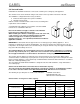
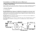
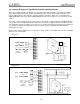
The unit has 4 holes for the air intake and gas vent outlet: 2 on the top and 2 on the back of the unit.
The humidifier is configured from the factory as follows:
• Exhaust vent through to the top of the humidifier;
• Air intake from the back.
Both the exhaust vent and air intake can be moved, according to the
requirements of the installation.
Vent and Intake pipe adapters are provided to convert the 80mm
Female size to a standard 3” Male size.
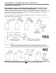
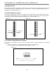
Note: Fit the exhaust vent pipe so that the section with the
inspection hole is always the first section.
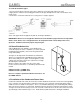
When installing the exhaust or intake pipes in the rear of the unit,
a rear clearance of 12” must be maintained. If the included
exhaust vent pipe does not have a pre-installed “test
plug/inspection hole”, one is provided, and must be installed to
applicable standards.
IMPORTANT: Vent materials must be approved for use for Category IV gas-burning appliances. These
materials are designed to be both air and watertight. You cannot use PVC for the exhaust because the gas
temperatures are too high. However, the air intake may be safely run in PVC or any other approved conduit, as
long as the ID of the tubing is at least 3”.
The maximum distance the vent and intake can be run is 120 equivalent combined feet or a maximum
pressure drop of 90 Pa (0.36” w.c.), whichever is more restrictive. Use the National Fuel Gas Code
and
the vent pipe manufacturer’s technical data to determine the venting length.
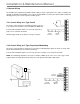
The vent pipe must be drained of condensate if it is run longer than 6 feet in any direction. When using a
condensate drain, a standard loop or p-trap must be used to prevent exhaust gases from venting into the drain.
Prior to using the appliance, ensure that the trap is filled with water and that the drain terminates in accordance
with local or national plumbing codes.
The vent adapter provided with the humidifier is designed to interface with standard 3”, single wall stainless
steel exhaust pipe.
Caution: The air intake must never be blocked or obstructed in any way.
The vent system must be installed and terminate so that proper clearances are maintained as cited in
local codes or the latest edition of the National Fuel Gas Code
, whichever is more restrictive.
The following are possible parts for outside vent terminations: 7390TEE Heat-Fab Inc.
02SVSTTX03 Z-Flex Inc.
SRTT-03 Flex-L International Inc.
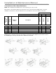
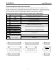
Characteristics of vent gases at 100% capacity:
Type of Fuel
Natural Gas Propane
Item Units UG045 UG090 UG045 UG090
KW
kcal/h
Nominal heat rate
BTU/hr
35.28
30,362
120,490
68.18
58,635
232,640
35.28
30,362
120,490
68.18
58,635
232,640
Flue gas flow rate Kg/s – lbs/min 0.0167 – 2.21 0.0318 – 4.21 0.0184 – 2.43 0.0297 – 3.93
Flue gas temperature °F 237 330 237 330
Percentage CO
2
in the flue
gas
% 9.2 9.2 11 11