
Specifications
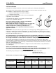
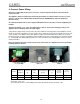

CAREL gaSteam
15
4. Connect Power Wiring
Before proceeding with the electrical connection, ensure that power has been removed from the
electrical circuit.
The appliance must be installed and electrically grounded in accordance with local codes or, in the
absence of local codes, with the National Electrical Code, ANSI/NFPA 70, and/or the CSA C22.1
Electrical Code.
An external fused disconnect, that complies with National and Local Codes, must be supplied by the
installer.
Should overheating occur, or the gas supply fails to shut off, shut off the manual gas valve to the
appliance before shutting off the electrical supply.
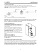
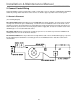
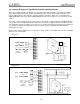
Verify that the supply voltage corresponds to the value indicated on the data label on the humidifier, located
inside the electrical compartment. Insert the power cables and ground connection through the inlet on the side
of the unit and secure with the strain relief. Attach the cables to the terminal blocks located in the electrical
junction box in the electrical compartment of the humidifier. Connect the power wiring to the terminals marked
L1, L2 and GND only. Wiring and internal line fuse sizes should be per the following table unless local codes
demand otherwise.
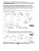
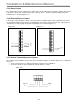
Note: The field junction box located on the bottom of the electrical compartment, must be used when
installing power to the unit.
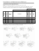
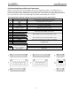
Model
voltage (1)
and phase
current
(A)
power
(W)
Steam Output (2)
(lbs/hr)
Wire Size
(3)
Internal
Fuses(3)
F1 & F2
Line
Fuses(3)
UG045 230 – 1~ 0.34 80 100 14 AWG 2A/ Slow 16A/ Fast
UG090 230 – 1~ 1.23 285 200 14 AWG 2A/ Slow 16A/ Fast
1) tolerance -15%, +10%
2) tolerance -10%, +5%
3) recommended values; electrical wiring must match all national and local electrical codes.
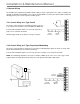
Power wiring junction box with
strain relief
Power wiring terminals
(L1, L2, & GND)
Power wiring junction box
installed