
Specifications

CAREL gaSteam
17
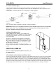
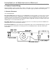
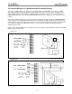
5.2 Connecting External Electrical Connections
Make the control connections by inserting the wires into the appropriate terminal. The terminal blocks are
located on the bottom of the electrical panel. Run the exterior wires through the side of the cabinet and hook
them to the terminal. All the terminal blocks are pictured below. The AL connector (supply voltage) is protected
by a metal enclosure, the wires passing through the grommet and attaching to the connector.
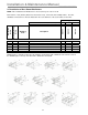
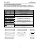
The following chart shows the external connections and their electrical characteristics:
terminal function electrical characteristics
1Z
input signal from high-limit
sensor
input impedance: 50Ω at 0-20mA or 4-20mA
60kΩ at 0-10V or 0-1V or 2-10V
2Z
GND
3Z
~32VDC derived from the 24Vac voltage regulator; max 250mA
4Z
12 VDC 5% precision; Imax=50mA
5Z
input from control sensor or
external controller
input impedance: 50Ω at 0-20mA or 4-20mA
60kΩ at 0-10V or0-1V or 2-10V
6Z
GND
7Z
remote enable
8Z
remote enable
Rmax=50Ω; Vmax=24VDC; Imax=10mA
9Z
alarm contact NO
10Z
alarm contact common
11Z
alarm contact NC
250V; 8A with resistive load; 2A with inductive load
12Z
dehumidify contact NO
13Z
dehumidify contact common
250V; 8A with resistive load; 2A with inductive load
1J
~32VDC derived from the 24Vac voltage regulator; max 250mA
2J
L+
3J
L-
4J
GND
standard RS-485
IK
NC contact
2K
common
3K
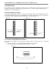
remote button switch terminal
block for drain control with
simultaneous disabling of
power supply
NO contact
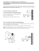
Note: The terminals 1K, 2K, and 3K are not visible as they are located inside the control electrical panel.
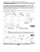
L1 L2 GND