
Specifications
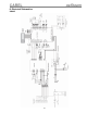
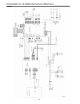


CAREL gaSteam
23
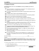
7. Installation Checklist
The following checklist needs to be reviewed BEFORE contacting your CAREL representative for
system start-up.
Proper electric power is connected to the control panel. This installation must be in
accordance with Local and National Electric Codes.
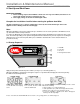
The nominal voltage provided to the humidifier must agree with the data on the units
rating label.
The power cable has been installed with proper strain-relief.
The electrical connections have been made according to the schematics provided.
All sensors are installed and connected per the instructions.
Airflow switch (if used) is set to close on airflow and open on airflow loss.
Hi-limit duct humidistat is set to open on humidity rise and is set for 85 to 90% RH.
All computer and/or DDC wiring is completed to the control panel and the signals are
verified.
All plumbing connections are complete and tested for leaks. NOTE: Flush new water
lines before the water solenoid valve. A water filter has been installed.
The drain line has a trap installed directly after the humidifier connection.
The gas line has been installed according to local or National Fuel Gas Codes. The
supplied gas shut-off valve must be installed external to the unit.
The vent must be constructed of Category IV vent pipe and installed according to
local or National Fuel Gas Codes.
Steam line is installed as instructed: with no obstructions or kinks present in the
steam distribution piping.
The return condensate line from the steam distribution line is installed and free of
obstructions. The condensate line must have a steam trap installed according to
instructions.
Checklist checked by: ______________________________________________ Date _____________
Company: _________________________________________________
Note: The above checklist MUST be returned before factory startup is begun. If any of
the above items are found to be not ready at time of startup, a second startup charge
may be assessed.
To start up the gaSteam humidifier, review the checklist above and the one below:
• The water and gas valves are open
• The fuses are installed and connected
• A terminal jumper has been placed across 7Z and 8Z on the plug in terminals (for testing only with no
high-limit or air flow sensors.)