
Specifications


CAREL gaSteam
27
8.5 Setting the Gas Burner
The burner comes tested and pre-calibrated from the factory for natural gas, but must be checked to
make sure it is regulating the combustion properly, by a qualified gas technician.
To perform the setting of the burner, the controller parameter bA (fan velocity) must be accessed and modified
on the controller.
Before applying voltage to the humidifier, it is necessary to verify that the jumper has been placed across the
terminal 7Z and 8Z on the relay board (this is used to disable the remote control function).
The Autotest is a cycle of the controller that checks the integrity of the water level sensors, and ensures that a
minimum amount of water will be present in the tank. You must wait until the Autotest has been successfully
completed, or bypass it, before you can access the parameter bA.
8.6 Forcing the Output for Burner Calibration
IMPORTANT WARNING: After accessing the parameters, do NOT press button 4 (PRG) - you may alter
other parameters if you do so.
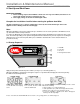
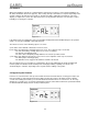
Refer to the faceplate drawing to the right. The burner output can be forced for calibration by:
1. Turning on the unit and waiting for the completion of the autotest;
2. Simultaneously press buttons 1and 4 (PRG and SEL) until the display '00'
appears;
3. Press buttons 2 and 3 as needed to enter the password '77' and press
button1 (SEL) to confirm. If entered correctly, the display will proceed to
'A0'; otherwise the controller display will default;
4. Press buttons 2 and 3 to cycle up or down through the parameters until
'bA' is displayed;
5. Press button 1 (SEL) to display the current value of the parameter,
6. Press buttons 2 and 3 to adjust the pace of the fan, from minimum (bC) to
maximum (bb) - note this is independent of the pre-ventilation speed;
• You have 10 minutes from the last keystroke to adjust the burner in each case before the unit exits this
menu and returns to the parameter screen.
• To exit the parameter screens, wait 1 minute without pressing any key and the controller will go back to
the default screen.
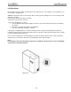
8.7 Preparing for the Analysis of the Vent Gas
Note: If vent pipe does not have the test plug pre-installed,
the test plug kit is included, and must be installed to code.
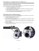
If the vent pipe has been installed vertically:
1) remove the plug T from the exhaust pipe of the humidifier
2) insert the probe of the combustion analyzer as shown;
3) perform the analysis.
If the vent pipe has been installed horizontally:
1) remove the plug T from the exhaust pipe of the humidifier;
2) insert the probe of the combustion analyzer as shown;
3) perform the analysis.
To complete the analysis, replace the plug in the vent pipe.
T
T