
User's Manual


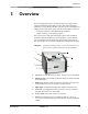


Table Of Contents
- 1 Overview
- Major internal assemblies
- How the laser imager works
- Print sequence
- Film sizes
- Automatic image quality and processing
- Configuring and monitoring the system (using the Web Portal)
- Enhancing serviceability with remote monitoring
- Agency compliance
- User guide conventions
- 2 Basic Operating Tasks
- Understanding the display screen
- Turning the power on and off
- Emergency shutdown or power loss
- Restarting the laser imager
- Working with film cartridges
- Checking film count
- Checking the size of the loaded film
- Film count is flashing "0"
- Inserting a new film cartridge
- Loading a different film size to match a print request
- Deleting pending jobs
- Making a test print
- Calibrating the laser imager for the installed film
- Opening or removing a cover
- Using the Web Portal to access additional functionality
- Accessing the Web Portal
- 3 Maintenance and Troubleshooting
- Overview: Status and error messages and codes
- Preventive maintenance
- Replacing the filter
- 550 code and Maintenance symbol
- Error indicators on the display screen
- Calibration error
- Required restart
- Film jams
- Using the Web Portal to gain more information on errors
- Understanding the codes on the Web Portal and the Display Screen
- Subsystem error codes and messages
- DICOM (Digital Imaging and Communications in Medicine)
- Printer
- Film Cartridge
- Job Manager
- Condition codes
- Correcting film jams
- Film jam code 116 / Jam in Area 1
- Film jam code 323 / Jam in Area 2
- Film jam code 324 or 325 / Jam in Area 2
- Film jam code 326 / Jam in Area 2 or 3
- Film jam code 543 / Jam in Area 3
- Film jam code 544 / Jam in Area 3
- Display Screen is not functional
- Calling for support
- 4 Film Technical Information
- General description
- Spectral sensitivity
- Image quality
- Environmental impact
- Storing and handling undeveloped film
- Dissipating odor
- Recycling film
- 5 Specifications
- Equipment specifications
- Operating space requirements
- Environmental requirements
- Temperature
- Relative humidity
- Altitude
- Surface levelness
- Environmental effects
- Power requirements
- Network requirements
- Publication History

1-2 9G3886_en 2011-03-31
Overview
Major internal assemblies
1 Exposure transport. Moves the film past the scanning laser beam.
2 Transport guides. Orient and center the film while moving the film from the supply to the imaging
portion of the laser imager.
3 DICOM Raster Engine (DRE). A computer board that receives, processes, and manages the images.
4 Feed rollers. Move the film through the laser imager.
5 Processor rollers. The processor uses heat to develop the image written onto the film by the laser in the
optics module. The rollers move the film through the processor assembly, holding the film against the
processor drum.
6 Processor drum. Provides the heat that processes the image on the film.
7 Airflow manifolds. Remove heat and processing odors from the processor assembly.
8 Pickup assembly. Lifts a single sheet of film from the supply cartridge and feeds it into the rollers.
9 Exit rollers. Moves the film from the processor area to the exit tray.
10 Rollback assembly. Rolls the film cartridge cover back so the pickup assembly can lift the film. When
the laser imager is not printing, the cover is closed over the film cartridge to protect the film from light.
11 Charcoal filter. Absorbs the odors caused by heat processing.
12 Optics module. Writes the image onto the film while the film is moved through the exposure transport.
13 Accumulator. The film feeds into the accumulator as it is imaged. When imaging is complete, the film
is sent from the accumulator up to the processor assembly where the heat is applied to process the image.
H210_1012HC
1
2
3
4
5
6
7
8
9
10
11
12
13