
User Manual

Remote controller
GENERAL INFORMATION
This remote controller is designed to separately control your ceiling fan speed and light brightness.
There are four buttons (HI, MED, LOW, OFF) to control the speed of the fan and off.
The light dimmer button will control the light brightness dimmer and off.
The blue indicator on the transmitter will light when one of the six buttons is pressed.
INSTRUCTION OF INSTALLATION AND OPERATION
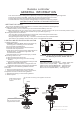
2.INSTALLING RECEIVER IN CEILING FAN
A. Safety precautions:
WARNING: HIGH VOLTAGE! Disconnect power by
removing fuse or switching off circuit breaker.
Do not use with solid state fans.
Electrical wire must meet all local and national
electrical code requirements.
Supply for fan must be 110/120 volt, 60Hz. Maximum
fan motor amps: 1.0, Maximum light watts: 190
incandescent or ballast.
Otherwise power can cause serious injury or death.
B. Installing receiver in fan:
a. Remove power from the circuit.
b. Remove ceiling fan canopy from the mounting
bracket.
c. Disconnect existing wiring between ceiling fan and
Supply in electrical junction box.
d. Make connections as follows, using the wire nuts
supplied: If other fans or supply wires are different
color, have this unit installed by qualified licensed
electrician.
e. Push all connected wires up into junction box.
f. Lay the brown antenna wire on top of the receiver,
and put the receiver into the mounting bracket.
g. Reinstall the canopy on the mounting bracket.
h. Restore power.
CONNECT TO
Green fan wire ....Bare supply wire
Red or Black receiver wire(AC IN L) ....Black supply wire
White receiver wire(AC IN N) ....White supply wire
White receiver wire(TO MOTOR N) ....White fan wire
Black receiver wire(TO MOTOR L) ....Black fan wire
Blue receiver wire(FOR LIGHT) ....Blue light wire
CAUTION: Ceiling Angle Shall Not Exceed 30 Degrees,
For Mounting Controller, Model AC8.3.T
ACN
ACL
ANT
COM
FAN
LIGHT
TRANSMITTER
INPUT
OUTPUT
RECEIVER
Use wire connecting nuts supplied with the fan
(FIG.3)
FROM POWER SOURCE
AC 110~120 VOLT 60Hz
3.5AMPS.
WHITE
AC
L
ACN
INPUT
OUTPUT
RED
BLUE
ANT
CANOPY
BLUE
B
LACK
WHITE
WHITE
B
L
A
CK
Use wire connecting nuts
supplied with the remote
WIRE NUT
R
EC
E
IVE
R
RECEIVER
CANOPY
(FIG.4)
ANTENNA PU T AT OUTSI DE
OF CANOPY BOX CAN GET
MORE OPERATION
DISTAN CE
LIGHT MUST BE KEPT AT THE ON POSITION
F A N M U S T B E K E P T A T T H E H I G H
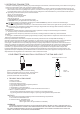
1.SETTING THE CODES
This unit has 16 different code combinations. To set the codes, perform the following steps:
A. Setting the codes on the transmitter:
a. Remove battery cover. Press firmly on the arrow and slide battery cover off.
b. Slide code switches to your choice of up or down position. (Factory setting is all up. Do not use this position. Use a
Small screwdriver or ball point pen to slide firmly up or down (Figure 1)).
B. Setting the codes on the receiver:
The Learn Key must be pressed with in 30 seconds, after pressing the Power button.
If not, please press the Power button to restart.
Keep pressing the button learn key in excess of 3 second it becomes a LEARN status.
The receiver can remember the last codes status .The light flash two times.
LEARN
LIGHT ON/OFF