Microscopy from Carl Zeiss Quick Guide LSM 710 / LSM 710 NLO and ConfoCor 3 Laser Scanning Microscopes LSM Software ZEN 2008 August 2008 We make it visible.
Contents Page Contents ................................................................................................................................. 1 Introduction............................................................................................................................ 2 Starting the System ............................................................................................................... 3 Introduction to ZEN – Efficient Navigation ........................................
Introduction This LSM 710 / LSM 710 NLO and ConfoCor 3 Quick Guide describes the basic operation of the LSM 710 / LSM 710 NLO and ConfoCor 3 Laser Scanning microscopes with the ZEN 2008 software. The purpose of this document is to guide the user to get started with the system as quick as possible in order to obtain some first images from his samples.
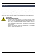
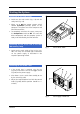
Starting the System Switching on the LSM system • Switch on the main switch (Fig. 1/1) and the safety lock (Fig. 1/2). • When set to ON the power remote switch labeled System/PC provides power to the computer. This allows use of the computer and ZEN software offline • To completely switch on the system, now press the Components switch to ON. This starts the other components and the complete system is ready to be initialized by the ZEN software. Switching on the X-Cite 120 or the HBO 100 mercury lamp Fig.
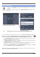
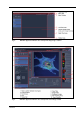
Starting the ZEN software • Double click the ZEN 2008 icon on the WINDOWS desktop to start the Carl Zeiss LSM software. The ZEN Main Application Window and the LSM 710 Startup window appear on the screen (Fig. 3) Fig. 3 ZEN Main Application window at Startup (a) and the LSM 710 Startup window (b and c) In the small startup window, choose either to start the system online ("Start System" hardware for acquiring new images) or in Image Processing mode to edit already existing images.
Fig. 4 ZEN Main Application Window after Startup with empty image container Fig.
Introduction to ZEN – Efficient Navigation ZEN - Efficient Navigation - is the new software for the LSM Systems from Carl Zeiss. With the launch of this software in 2007 Carl Zeiss sets new standards in application-friendly software for Laser Scanning Microscopy. The ZEN 2008 Interface is clearly structured and follows the typical workflow of the experiments performed with confocal microscopy systems: On the Left Tool Area (Fig.
The Pro-Basic concept ensures that tool panels are never more complex than needed. In Basic Mode, the most commonly used tools are displayed. For each tool, the user can activate Pro Mode to display and use additional functionality (Fig. 6). Fig. 7 ZEN Window Layout configuration More features of ZEN 2008 include: • The user can add more columns to the Left Tool Area or detach individual tools to position them anywhere on the monitor. To add a column, drag a tool group by the title bar (e.g.
Setting up a new image document and saving your data To create a new image document in an empty image container, click the "Single" or the "Start" button. The new document is immediately presented in the Open Images Area. Remember, an unsaved 2D image in the active image tab will be over-written by a new scan. Multi-dimensional scans or saved images will never be over-written and a new scan will then automatically create a new image document.
Advanced data browsing is available through the File Browser (Ctrl-F or from the File Menu). The File Browser can be used like the WINDOWS program file browser. Images can be opened by a double-click and image acquisition parameters are displayed with the thumbnails (Fig. 9). For more information on data browsing please refer to the detailed operating manual. Fig.
Turning on the lasers • Open the Laser Tool in the left tool area (always the first in the list) and activate the lasers you need for your experiment (Fig. 10). Remember, the argon multi-line laser has to first be put to standby for a 5 minute warm-up before it changes to on. • Zeiss recommends operating the Argon multi-line Laser at a tube current of about 6 A (∼50 % output). This is the best compromise between laser stability/power and laser life-time. (tube-current control can be found in Pro Mode).
Setting up the microscope Changing between direct observation, camera detection and laser scanning mode The Ocular, Camera and LSM buttons switch the beam path and indicate which beam path is currently in use for the microscope: • Click on the Ocular button to change the microscope beam path for direct observation via the eyepieces of the binocular tube, lasers are blocked.
Setting the microscope for reflected light • Click on the Reflected Light icon to open the X-Cite 120 Controls and turn it on. • Click on the Reflected Light shutter to open the shutter of the X-Cite 120 lamp / HBO100. • Click on the Reflector button and select the desired filter set by clicking on it. Storing the microscope settings Microscope settings can be stored as configurations (Fig. 13) by typing a config name in the pull-down selector and pressing the save button.
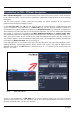
Configuring the beam path and lasers • Click on the LSM button. Choosing a configuration Simultaneous scanning of single, double and triple labeling: − Advantage: faster image acquisition − Disadvantage: Eventual cross-talk between channels Sequential scanning of double and triple labeling; line-by-line or frame-by-frame: − Advantage: Only one detector and one laser are switched on at any one time. This reduces crosstalk.
Settings for track configuration in Channel Mode • Select Channel Mode if necessary (Fig. 15). • Click on the LSM tab (Fig. 14). The Light Path tool displays the selected track configuration which is used for the scan procedure. • You can change the settings of this panel using the following function elements: Fig. 15 Imaging Setup tool for a single track (LSM) Activation / deactivation of the excitation wavelengths (check box) and setting of excitation intensities (slider).
• For storing a new configuration enter a desired name in the first line of the Configurations list box (Fig. 17) and click Store. • For loading an existing configuration select it from the list box and click on the button. Load • For deleting an existing configuration select it in the list box and click on Delete. Fig.
Scanning an image Setting the parameters for scanning • Select the Acquisition Mode tool from the Left Tool Area (Fig. 18). • Select the Frame Size as predefined number of pixels or enter your own values (e.g. 300 x 600) in the Acquisition Mode tool. Click on the Optimal button for calculation of appropriate number of pixels depending on objective N.A. and λ. The number of pixels influences the image resolution! → Fig.
Setting scan averaging Averaging improves the image by increasing the signal-to-noise ratio. Averaging scans can be carried out line-by-line or frame-by-frame. Frame averaging helps to reduce photo-bleaching, but does not give quite as smooth of an image. • For averaging, select the Line or Frame mode in the Acquisition Mode tool. • Select the number of lines or frames to average. Adjusting pinhole size • Select the Channels tool in the Left Tool Area.
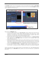
Image acquisition Once you have set up your parameter as defined in the above section, you can acquire a frame image of your specimen. • Use one of the Find, Fast, Continuous, or Single buttons to start the scanning procedure to acquire an image. • Scanned images windows. are shown in separate • Click on the Stop button to stop the current scan procedure if necessary. Select Find for automatic preadjustment of detector gain and offset. Fig.
The scanned image appears in a false-color presentation (Fig. 22). If the image is too bright, it appears red on the screen. Red = saturation (maximum). If the image is not bright enough, it appears blue on the screen. Blue = zero (minimum). Adjusting the laser intensity • Set the Pinhole to 1 Airy Unit (Fig. 23). • Set the Detector Gain high. Fig. 22 Image Display Fig. 23 Channels tool • When the image is saturated, reduce AOTF transmission in the Laser control section of the Channels Tool (Fig.
Scanning a Z stack • Open the Z Stack tool in the Left Tool Area. • Select Mode First/Last on the top of the Z Stack tool. • Click on the Action Button area. button in the A continuous XY-scan of the set focus position will be performed. • Use the focus drive of the microscope to focus on the upper position of the specimen area where the Z Stack is to start. • Click on the Set First button to set the upper position of the Z Stack.
Storing and exporting image data • To save your acquired or processed images, click on the Save or Save As button in File Menu button at the (Fig. 25/1), click on the bottom of the File Handling Area (Fig. 25/2) or click the (Fig. 25/3). button in the Main Toolbar Fig. 25 Save Image buttons in ZEN Fig. 26 Save as window Fig. 27 Export window • The WINDOWS Save As window appears. • Enter a file name and choose the appropriate image format.
Using the ConfoCor 3 module • Click on the LSM button. • Use the ConfoCor 3 Tool Group in the Left Tool Area to acquire and analyze FCS data. → Fig. 28 ConfoCor 3 Tool Group Setting a configuration • Open the Measure toolbar to access experiment parameter controls. • Select the System Configuration controls in the Measure tool. The Light Path and Pinhole panels of the Measure window display the selected track configuration which is used for the FCS procedure and the pinhole size (see Fig. 29). Fig.
You can change the settings of this panel using the following function elements: Activation / deactivation of the excitation wavelengths (check box) and setting of excitation intensities (slider). Open the Laser Control tool via the Laser icon. Selection of the main dichroic beam splitter (HFT) or secondary dichroic beam splitter (NFT) position through selection from the relevant list box. Selection of a block filter through selection from the relevant list box.
Starting a measurement • Open the Measure toolbar to access experiment parameter controls. • Select the Acquisition controls in the Measure tool. The Light Path and Pinhole panels of the Measure window display the selected track configuration which is used for the FCS procedure and the pinhole size (see Fig. 30). Fig.
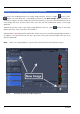
Press the New button to open a new FCS diagram into an image container. If a measurement is triggered, all data are displayed in that window if highlighted. Press the Start button to trigger a measurement. All defined positions will be approached consecutively. Press the Single button to trigger one measurement at the highlighted or first defined position. Press the Stop button to end a measurement. All data accumulated so far will be available and can be stored.
Fig. 31 FCS Correlation diagram You have the following function elements: Activate the FCS Correlation panel to display measured data (Fig. 31). Press the View Options button to define the graph you want to display. Press the Count rate button to display the count rate trace. Press the Correlation button to display the correlation function. Press the Photon counting histogram button to display the photon distribution per time unit.
Press the Data Options to handle your data. Press the Save Data button to open the Save window. You can save the whole data set in an ANSI text format. Optionally you can save the raw data trace if that option was set in the FCS Options. Pressing the Reuse button will set the system configuration to exactly the same values, as used in the experiment. Pressing the Reload button will open the current measurement, if stored raw data are available.
You have the following options: Activate the FCS Fit panel to display fitted data (Fig. 32). Set the red and blue bars to define the start and end points of the curve fit window. Load a predefined model from the Model drop-down menu. You can assemble a model by pressing the Model tool in the ConfoCor tool group. Define the conditions of the fit by activating / deactivating terms, setting the type of a parameter (fixed, free, or start value), defining limits and globally link parameters in the Model table.
Switching off the system • Click on the File button in the Main Menu bar and then click on the Exit button to leave the ZEN 2008 software. • If any lasers are still running you should shut them off now in the pop-up window indicating the lasers still in use. • Shut down the computer. • Switch off the Ar-ML laser with 1 the standby switch (Fig. 2/3) and 2 the main switch (Fig. 2/2), and wait until the fan of the Argon laser has switched off. Don’t turn the key switch yet.