Du line ® Fieldbus Installationbus Configuration Software G3800 X015 User Manual Preliminary Data December 2002 Gross Automation (877) 268-3700 · www.carlogavazzisales.com · sales@grossautomation.
G 3800 X015 Configuration Software October 2002 Table of Contents 1. Introduction 1.1. Start-up 1.1.1. Hardware requirements 1.1.2. Installation 1.1.3. Start-up of program 1.2. Functions in the main window 1.2.1. File menu 1.2.2. Edit menu 1.2.3. Select menu 1.2.4. Tools menu 1.2.5. Help menu 1.2.6. Configuration of channel functions 1.3. Basic Setup 4 4 4 4 4 5 5 6 7 7 8 9 10 2. Objects 2.1. General 2.2. Standard objects 2.2.1. Blank channel (no function) 2.2.2. The push-button function 2.2.3.
G 3800 X015 Configuration Software October 2002 © 2002 Carlo Gavazzi Industri A/S. All rights reserved Gross Automation (877) 268-3700 · www.carlogavazzisales.com · sales@grossautomation.
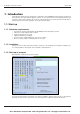
G 3800 X015 Configuration Software October 2002 1. Introduction The G38xx15 program has been designed for configuration of the G3800X015 master generator. All functions in the generator are represented by graphic symbols. To each channel function are related parameters and comments, which can be edited locally in the PC and transferred to the master generator through RS232. Likewise, data from the master generator can be uploaded and edited. 1.1. Start-up 1.1.1.
G 3800 X015 Configuration Software October 2002 1.2. Functions in the main window 1.2.1.
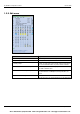
G 3800 X015 Configuration Software October 2002 1.2.2. Edit menu 6 Menu Item: Explanation: Basic Setup: Basic setup of the G3800X015 generator Logic Setup: Configuration of logic functions Holiday Setup: Setup of holiday period. The holiday setup is active when the current date falls within any of the set time intervals. SMS (only valid for G38001015) Basic setup of the SMS messaging functions facilitated by the built-in GSM modem.
G 3800 X015 Configuration Software October 2002 1.2.3. Select menu Menu Item: Explanation: Language: Select between 3 languages. By using the “Select new” menu, other languages can be inserted in the 3-language menu. Serial port: Selection of Com 1, Com 2, Com 3 or Com 4 port, for connection of the G3800X015 Generator. 1.2.4. Tools menu Generator firmware: In this menu it is possible to download a new firmware file to the Generator.
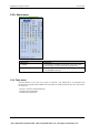
G 3800 X015 Configuration Software October 2002 1.2.5. Help menu 8 Menu Item: Explanation: General information: You can call the Help menu at any time by pressing F1. About program: Shows the opening screen © 2002 Carlo Gavazzi Industri A/S. All rights reserved Gross Automation (877) 268-3700 · www.carlogavazzisales.com · sales@grossautomation.
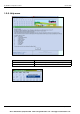
G 3800 X015 Configuration Software October 2002 1.2.6. Configuration of channel functions When the basic settings have been made under “Basic Setup”, the functions of the remaining channels to be used are defined as follows: Activate one of the channels, then click on the right mouse button for pop-up menu. Click on the desired channel function with the left mouse button. The channel is thereby assigned a symbol indicating the selected channel function.
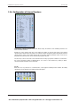
G 3800 X015 Configuration Software October 2002 1.3. Basic Setup General description The text window is for entering general information, eg name of user, date of configuration, reference to documentation, etc. No. of channels For selection of the number of channels desired in the system. The minimum is 8, the maximum is 128 in one Dupline network. Auto-start Dupline on short-circuit In case of a short-circuit on Dupline, the Generator shuts down the Dupline signal.
G 3800 X015 Configuration Software October 2002 2. Objects 2.1. General The objects are the specific functions of the G 3800 X015. The functions are assigned to channels, and the associated parameters determines the operation of the channels. © 2002 Carlo Gavazzi Industri A/S. All rights reserved Gross Automation (877) 268-3700 · www.carlogavazzisales.com · sales@grossautomation.
G 3800 X015 Configuration Software October 2002 2.2. Standard objects 2.2.1. Blank channel (no function) • Function: None • Application: Activation of output channels through master functions or logic setups • Insert with mouse (“Blank channel”) Description The use of blank channels in Dupline is based on the circumstance that in- and output are independent of each other.
G 3800 X015 Configuration Software October 2002 2.2.2. The push-button function • Function: Monostable • Application: Connection of push-button switches and contacts for load switching • Also Normally Closed function • Select with mouse (“Push button”) or short-cut key “0” (Zero) Description The push-button function - the most simple object of the Dupline Master Generator - makes it possible to connect any type of push button switch and contact to the Dupline bus.
G 3800 X015 Configuration Software October 2002 Application Example Task: A lamp is to be switched on and off by means of a switch. Solution: Use for example the universal input module to provide the input signal and configure one of the inputs for address A1. Assign the same address to one of the outputs of a relay module. Finally, configure channel A1 in the Master Generator as push button function.
G 3800 X015 Configuration Software October 2002 2.2.3. The toggle switch function • • • • Function: Bistable Flip-Flop Application: Connection of switches and contacts for load switching Can be used in intruder alarm systems Select with mouse (“Toggle switch”) or short-cut key “F” Description The toggle switch function makes it possible to simulate the operation of a toggle switch: Pressing the switch once activates the output, pressing the switch once more de-activates the output again.
G 3800 X015 Configuration Software October 2002 Application Example Task: A lamp is to be switched on and off by means of a conventional switch. Solution: Use for example the universal input module to provide the input signal and configure one of the inputs for address A1. Assign the same address to one of the outputs of a relay module. Finally, configure channel A1 in the Master Generator as switching function.
G 3800 X015 Configuration Software October 2002 2.2.4. Timer/Recycler • • • • • Function: Timer or Recycler Application: Switching with on- or off-delay or recycler Activation by signal or impulse Activation by additional channel or flag Select with mouse “Timer” or short-cut key “T” Description This object makes it possible to select between two modes of operation: timer and recycler.
G 3800 X015 Configuration Software October 2002 Parameter Description Enabled by address Entering of an additional channel (A1..P8) or flag (W1..Z8) which will also enable the timer function. To prevent locking, the channel assigned to the timer itself must not be used. If the additional signal is an impulse, select the option Activation by pulse.
G 3800 X015 Configuration Software October 2002 Recycler IN t TE TA OUT t1 t2 t3 t4 PMan_TTimer_2a t The impulse is generated shortly after the input has switched on at time t1. A pulse cycle consists of the Ontime tE and the Off-time tA. When the input is switched off, the pulse cycle also ends. Application Example Task: A fan in a bathroom is to start 5 min after the light has been switched on and run for 10 min.
G 3800 X015 Configuration Software October 2002 2.2.5. Real-time clock • • • • • Function: Real-time clock with week and holiday planner Application: Time-controlled switching on and off of loads Also applicable as switching function Holiday setting can be performed centrally for all clocks Select with mouse “Real-time” or short-cut key “R” Description The real-time clock enables on- and off-switching of loads in relation to the internal time setting of the Master Generator.
G 3800 X015 Configuration Software October 2002 t1: The real-time clock activates the channel at the pre-defined time without affecting the input channel. t2: By activation of the input, the output switches off directly. t3: By activating the input once more, the output switches on again. t4: At the set Switch off time, the input is always deactivated. t5: The output can always be activated againg through the output. Application Example Task: A lamp is to be switched on and off by means of a switch.
G 3800 X015 Configuration Software October 2002 2.2.6. Master function • Function: Simultaneous on- and off-switching of multiple toggle switch functions, real-time clocks, etc, upon activation of input. • Integrated real-time clock with four switch times • Application: Simultaneous off- on on-switching of multiple loads, calling lighting scenes in connection with dimmers. • Select with mouse (“Master function”) or short-cut key “M”.
G 3800 X015 Configuration Software October 2002 Parameter Description Address matrix Mark the addresses to be switched on by the master function with “1” and the addresses to be switched off with “0”.* Addresses marked with “x” are not affected. Addresses which are automatically marked with a red line cannot be controlled by a master function, eg master functions, roller blind controls, etc.
G 3800 X015 Configuration Software October 2002 Application Example Task: The master function is to control four lamps and two dimmers in a building. - Master on: Switches all lamps on and sets dimmer at 100%. - Master off: Switches all lamps off and sets dimmer at 0%. - Lighting scene for living room: lighting scene 6 (factory setting: 85%) is to be called by both dimmers. Solution: Three push buttons are configured on addresses A1 to A3 to initiate the master function for calling the lighting scene.
G 3800 X015 Configuration Software October 2002 2.3. Special objects 2.3.1. Analog sensors • Function: Transmission and output of analog values (from temperature, light and other sen sors) to perform switching functions • Application: Display of analog (AnaLink) values on text display/touchscreen: load switching (for example heating elements, lamps, roller blinds) in relation to temperature or outdoor light, etc.
G 3800 X015 Configuration Software October 2002 Parameters Configuration window of the analog sensor function: When the Configuration Software has been connected to the master, the actual values are shown: In general, the operation of sensors depends on the purpose of using the values: Showing data on PC, Touchscreen or Text display In this case, the parameters “Control output” and “Alternative input” should not be activated, because in that case the analog value will only be transmitted and not display
G 3800 X015 Configuration Software October 2002 The following table gives an overview of all parameters: Parameter Description Function Select the function of an ordinary measuring sensor, light sensor, wind or temperature sensor. Basically, all functions operate in the same way. Disable address When the channel or flag entered here is activated, all switching operations of the sensor are disabled. The value can be overwritten at any time and deleted by the Delete-key.
G 3800 X015 Configuration Software October 2002 Time characteristics Sensor for display of measuring values In this application, the displayed value follows the actual value after a short delay. Note: Upon switch-on of the sensor or the Dupline bus, the actual sensor value is only reached after a time elapse of 30 s. This time is needed by the system to calculate the value accurately.
G 3800 X015 Configuration Software October 2002 Application Example Task: A heating element is to keep the room temperature between 19°C and 21°C during daytime. At night, the temperature must be lowered by 4°C. A temperature sensor located in the room is coded for address A2 and displays the temperature on a Touchscreen.
G 3800 X015 Configuration Software October 2002 2.3.2. Motion detector • • • • • Function: Includes motion detectors or similar input modules in the Dupline system.
G 3800 X015 Configuration Software October 2002 Time characteristics In the following figure, “IN” is the input channel of the motion detector or the contact, while “OUT” is the output signal of the same channel. In addtion, the object “Motion detector” has been integrated in the intruder alarm system (whose alarm siren can also be seen in the below diagram). The number of impulses has been set to “3”.
G 3800 X015 Configuration Software October 2002 Application Example Task: A floor lighting is to switch on automatically for 5 minutes with PIR sensor G 8910 1127 and also serve as intruder alarm when the house is empty. Solution: G 8910 1127 must be connected to the Dupline bus and given an address (here A1). In this example, increase of the signal transmission time through the DIP switch is to be switched out.
G 3800 X015 Configuration Software October 2002 2.4. Alarm functions 2.4.1. Overview This chapter will assist you in using the four different Dupline alarm systems: 1. ISA-alarm (chapter 2.4.3) This general alarm system develped acc. to ISA specifications is very flexible and has formed the basis of the development of the other alarms systems. Application areas include temperature- and level control as well as plants requiring ordinary alarm functions. 2. Smoke alarm (chapter 2.4.4.
G 3800 X015 Configuration Software October 2002 2.4.3. ISA Alarm • Function: General alarm system with inclusion of Passive detector, Active detector, Acknowledgement, Reset, Lamp test and Alarm siren • Application: Monitoring of contacts and other alarm sources. • Select with mouse (“ISA alarm”) or short-cut key “A” Description The purpose of the ISA-Alarm is to serve as a general alarm system acc. to the ISA specifications. The system supports two operation modes: 1.
G 3800 X015 Configuration Software October 2002 If a contact is activated during resetting, the system triggers off a new alarm When this object is configured, the operation mode “Standard” is automatically selected. Lamp test: This object makes it possible to test the function of lamps indicating the status of the alarm contacts. All alarm channels are activated upon actuation of the lamp test button. Alarm siren: The alarm siren indicates the occurence of an alarm.
G 3800 X015 Configuration Software October 2002 On-delay Enter a time value in seconds (0..255) for which the alarm signal is delayed upon activation of the alarm contact. Acknowledge No configuration possibilities. Reset No configuration possibilities. Lamp test No configuration possibilities. Alarm siren Siren time This setting determines for how long the alarm output is to remain activated in the case of alarm. The value can be between 0 and 60 min.
G 3800 X015 Configuration Software October 2002 The above illustration shows the normal sequence and reset of an alarm in the operation mode “Standard”: t1: When all contacts are in off-position, the Master Generator alerts the alarm system automatically upon loading of the application. t2: After elapse of on delay TEV, the Master Generator activates the alarm siren and causes the output of the source channel to flash.
G 3800 X015 Configuration Software October 2002 Application Example Task: In a chemical factory, eight laboratories are to be provided with alarm switches. Upon activation of an alarm button, the fire staff of the factory is informed via a siren. When the fire staff has acknowledged the alarm, they go to the lab where the alarm was started. Solution: The alarm switches are coded for channels A1 to A8. The source of the alarm is indicated on a panel whose LED is activated via a mimic display.
G 3800 X015 Configuration Software October 2002 2.4.4. The Smoke Alarm • Function: Fire alarm system including Passive detector, Active detector, Reset, Alarm Siren and Alarm signal • Application: Wiring of smoke/fire indicators to an alarm system • Select with mouse (“Smoke alarm”) or short-cut key “S” Description The purpose of the Smoke Alarm is an alarm system consisting of smoke and fire indicators integrated as Passive or Active detectors.
G 3800 X015 Configuration Software October 2002 Parameters: Parameter Description Passive detector Disable address Enter an address (A1..P8) or a flag (W1..Z8) whose activation (“1”-signal) will leave out the Passive detector function of the monitoring system whereby it cannot trigger off any further alarms. Active detector Disable address Enter an address (A1..P8) or a flag (W1..
G 3800 X015 Configuration Software Parameter October 2002 Description Alarm siren Siren time With this setting, you determine the duration of the activation of the alarm output upon the occurence of an alarm. The value can lie between 0 and 60 min. The entered value is automatically adopted by the Common Siren. Alarm signal Alarm signal delay With this setting, you determine the time to elapse after switching on of the alarm siren till the alarm signal is activated.
G 3800 X015 Configuration Software October 2002 Time characteristics Passive detector (IN) t TEV Passive detector (OUT) t Reset (IN) t TR TR Reset (OUT) t Siren t TM Alarm signal t1 t2 t3 t4 t5 t6 t PMan_TSmoke_1a The above illustration shows the normal sequence and reset of an alarm: t1: When power supply is connected, the system becomes alert after elapse of the set reset delay TR, indicated by reset of the reset output. t2: After a short delay (approx.
G 3800 X015 Configuration Software October 2002 Application Example Task: In a residential building, eight rooms are to be equipped with smoke detectors. When an alarm occurs, a siren switches on and the fire authorities are notified. Solution: The alarm channels of the smoke detector are assigned to channels C1 to C8. The alarm source is indicated on a panel whose LED is activated by mimic display. The addresses correspond to those of the alarm contacts.
G 3800 X015 Configuration Software October 2002 2.4.5.
G 3800 X015 Configuration Software October 2002 Manual armouring: This object makes it possible to include a push button to enable and reset the alarm. The object only enables the alarm contacts for which no or a deactivated disable address has been entered. Manual armouring thus partly enables alarms. Upon activation of manual armouring, the armouring delay begins to run. During this time, the channel generator ignores activated alarm contacts.
G 3800 X015 Configuration Software October 2002 Parameters Parameter Description Passive detector Disable address Enter an address (A1..P8) or a flag (W1..Z8) whose activation (“1”-signal) will leave out the Passive detector function of the monitoring system whereby it cannot trigger off any further alarms. Active detector Disable address Enter an address (A1..P8) or a flag (W1..
G 3800 X015 Configuration Software Parameter October 2002 Description Alarm siren Siren time With this setting you determine how long the alarm output is to remain activated when an alarm occurs. The value can lie between 0 and 60 min. The system becomes alert again, when the siren time has elapsed and no alarm contact is activated any more. A value entered here is automatically adopted by the Common siren.
G 3800 X015 Configuration Software October 2002 Time characteristics Passive detector (IN) t TFV Passive detector (OUT) t TEV Manual armouring (IN) t Manual armouring (OUT) t TAV TA Alarm siren PMan_TBurglar_1a t TM Alarm signal t1 t2 t3 t4 t5t6 t7 t8 t The above illustration shows the normal sequence of an alarm as well as early acknowledgement and the switching of the system back into the alert state through the Manual Armouring option: t1: When the Master Generator is switched on,
G 3800 X015 Configuration Software October 2002 t7: Activation of the Manual Armouring will acknowledge the alarm, and the Manual Armouring output will be reset. t8: Activating the Manual Armouring once more will bring the system back into the alert state - after the armouring delay TFV. Application Example Task: In a residential building, eight rooms are to be equipped with window and door contacts. All light switches as well as two motion detectors are to be included in the system.
G 3800 X015 Configuration Software October 2002 2.4.6. The Water Alarm • Function: Water alarm system including Passive detector, Active detector, Reset, Siren and Alarm signal • Application: Wiring of water indicators, eg the water stop sensor, to an alarm system • Select with mouse (“Water alarm”) or short-cut key “W” Description The purpose of the Water Alarm is an alarm system consisting of water sensors integrated as Passive or Active detector.
G 3800 X015 Configuration Software October 2002 Parameters Parameter Description Passive detector Disable address Enter an address (A1..P8) or a flag (W1..Z8) whose activation (“1”-signal) will leave out the Passive detector function of the monitoring system whereby it cannot trigger off any further alarms. Active detector Disable address Enter an address (A1..P8) or a flag (W1..
G 3800 X015 Configuration Software Parameter October 2002 Description Alarm siren Siren time With this setting, you determine the duration of the activation of the alarm output upon the occurence of an alarm. The value can lie between 0 and 60 min. The entered value is automatically adopted by the Common Siren. Alarm signal Alarm signal delay 52 With this setting, you determine the time to elapse after switching on of the alarm siren till the alarm signal is activated.
G 3800 X015 Configuration Software October 2002 Time characteristics Passive detector (IN) t TEV Passive detector (OUT) t Reset (IN) TR TR t Reset (OUT) 3s t 57s t TM Alarm signal t1 t2 t3 t4 t5 PMan_TWater_1a Siren t The above illustration shows the normal sequence and reset of an alarm: t1: When power supply is connected, the system becomes alert after elapse of the set reset delay TR, indicated by reset of the reset output. t2: An alarm contact is activated.
G 3800 X015 Configuration Software October 2002 Application Example 54 Task: In a residential building, eight rooms are to be protected against water damage. When an alarm occurs, a siren switches on and the house owner is informed by means of an SMS-message. The room in question should be recognizable on a panel. Solution: The alarm channels of the water stop sensors are assigned to channels G1 to G8. The alarm source is indicated on a panel, whose LED is activated by a mimic display.
G 3800 X015 Configuration Software October 2002 2.4.7. Common Siren • Function: Common output of ISA-, Smoke-, Intruder- and Water alarm • Application: Output of several alarms on one siren in addition to or in replacement of alarm system specific sirens • Select with mouse (“Common Siren”) Description The Common Siren offers the possibility of transmitting the alarms of all alarm systems on one channel. The alarm of the siren output behaves in the same way as the individual alarm sirens.
G 3800 X015 Configuration Software October 2002 2.5. Roller blind control 2.5.1. Decentralized roller blind up-down function • Function: Up-Down control of roller blind motors • Application: Control of motors for roller blinds, sun blinds and roof windows through Dupline modules G 3430 4249. • Run time and Switch time individually adjustable • Tilted blinds for sun blinds and priority control for example for wind sensor.
G 3800 X015 Configuration Software October 2002 Connection of several motors Simultaneous activation of several motors can be achieved by: 1. connecting all motors to separate outputs and 2. assigning the same address to all up-channels as well as all down-channels. We strongly advise against connecting two or more motors in parallel to one output channel. The flexible way of controlling several motors centrally or group-wise is to use the Roller blind master function.
G 3800 X015 Configuration Software October 2002 Parameters Parameter Description Roller blind control (Decentralized Up-Down) Roll time Insert the times (seconds) for which the motor is to run in each direction. The value must be within 0 and 255 s. The selected time interval should ensure that the roller blinds can reach the end positions in both directions where an end position contact must switch the motor off. Intermediate values allows shadow, for example.
G 3800 X015 Configuration Software October 2002 Time characteristics TV TV Up-button t TV Down-button Up-channel TU t TL Down-channel t1 t2 t3 t4 t5 t6 t7 t PMan_TRollerUpD_1a t The above illustration is based on a roller blind application with adjustment of tilting blinds (Reverse Up time TV of 3 s). t1: The button for the up-direction is activated. Since the impulse is shorter than the Reverse Up time TV (3 s), the motor stops when the button is released.
G 3800 X015 Configuration Software October 2002 Application Example Task: Control of several roller blinds as well as a roof window in a building. The system should include groupwise control for two different floors as well as master control of all roller blinds together. To protect the roller blinds, a wind sensor and a rain sensor are installed. The roller blinds are to roll down by rain and up by wind, and wind has priority. The roof window is to close by rain.
G 3800 X015 Configuration Software October 2002 2.5.2. Roller blind master • • • • • • Function: Group-wise or master control of decentralized roller blinds Application: Group-wise or master control of motors for roller blinds, Roll time with priority over individual roll times adjustable Simultaneous or sequential roller blind start selectable Reverse Up time for tilting blinds when end position reached.
G 3800 X015 Configuration Software October 2002 Parameters Parameter Description Roller blind master Operation mode The setting determines whether the roller blinds are started simultaneously or sequentially. With the setting “Sequentially”, the roller blinds start and stop successively at 1 second intervals. This time interval is also observed in connection with change of direction or tilting blind (Reverse Up time). This time interval does not affect the set roll time.
G 3800 X015 Configuration Software October 2002 Time characteristics Up-button central t Down-button central t TU TU TL TR Up-channel (roller blind 1) t Down-channel (roller blind 1) t TV TV TU TL Up-channel (roller blind 2) t t1 t2 t3 t4 t5 t6 t7 t PMan_TRollerMaster_1a TV The above illustration is based on a roller blind master application with sequential operation mode and a Reverse Up time TR. t1: The button for the up-direction is activated.
G 3800 X015 Configuration Software October 2002 2.6. Counter and Multiplexer 2.6.1. Multiplexer (transmission of counter values) • Function: Object for detection of max. 128 counter values • Application: Registration of energy and operating hours with counter module G 4420 7401. • Configuration through the option Counter and Mux Analog Setup in the edit menu. Description The counter channels with the sum sign ∑ are for transmission of counter values.
G 3800 X015 Configuration Software October 2002 Parameters Parameter Description Multiplexer (Detection of counter values) Counter range With this setting made under , you select the range of counter values. Depending on the range, a coresponding number of channel groups, beginning by “B” are reserved: Counter ranges Reserved groups --- None (counter operation switched off) 0..99 B..C 0..9999 B..D 0..999999 B..E 0..99999999 B..
G 3800 X015 Configuration Software October 2002 2.6.2. Multiplexer (transmission of analog values) • Function: Object for detection of max. 112 analog values • Application: Fast transmission of multiplexed analog values through Dupline analog modules • Configuration under the option “Multiplexer channels” in the Basic setup Description The (original) multiplexing of analog values makes it possible ot read and write Dupline multiplex analog values.
G 3800 X015 Configuration Software October 2002 Processing of analog values As opposed to the counter values, it is not only possible to visualize the analog multiplex values through the Modbus communication interface, but also to change them. There are basically two possibilities of value processing: 1. Representing the values in visualization software or operator panel (eg on a PC with the Dupline WebServer). 2.
G 3800 X015 Configuration Software October 2002 3. Logic Setup 3.1. Introduction The preceding chapters have illustrated the simplicity of configuring channels with the pre-defined objects. Praxis, hower, is not always so simple - for example when the outdoor lamps must be controlled in relation to the time of day, or the roller blinds in relation to light or weather or conditions.
G 3800 X015 Configuration Software October 2002 Designation Values Description Abb. (1) Output A1..P8 W1..Z8 Channel or flag whose status is to be changed A Input 1 A1..P8 W1..Z8 -,/,\ Channel or flag causing the first part of the conditions for the change in output status E1 Function AND, OR, XOR The logic operand connection the two inputs Fkt Input 2 A1..P8 W1..
G 3800 X015 Configuration Software October 2002 The following tables summarize the results of the logic setups: E1 0 1 0 1 AND E2 0 0 1 1 E1 0 1 0 1 A 0 0 0 1 OR E2 0 0 1 1 A 0 1 1 1 E1 0 1 0 1 XOR E2 0 0 1 1 A 0 1 1 0 Example: If in the XOR-function, both input 1 (E1) and input 2 (E2) have the value “1”, the output (A) will assume the value “0”. 3.3.2.
G 3800 X015 Configuration Software October 2002 Time characteristics E1 t E2 t A1 t1 t2 PMan_003a t Two conditions must be fulfilled (AND): E1 must be active and E2 must trigger on leading edge. This only takes place at t1 (the dotted line to the left). If the signal on E1 goes Off (dotted line to the right), output A will also be reset. It is assumed that the channel set as output A is configured for a “toggle switch function”, for example.
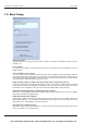
G 3800 X015 Configuration Software October 2002 4. GSM Modem functions (only valid for G38001015) 4.1. SMS Setup The G38001015 Master Generator has a built-in GSM Modem which enables Monitoring and control of Dupline signals via SMS messages to/from mobile GSM telephones. There are 3 different ways to use SMS messaging: • • • The Master Generator can be programmed to send out event-based SMS messages. The event can be a channel switching ON or OFF, or it can be an analog signal crossing a set-point.
G 3800 X015 Configuration Software Parameter Dial Out Phone Numbers Max. User Response time October 2002 Description Up to 4 telephone numbers to which the SMS messages shall be sent can be entered. The country code must be included in the numbers (e.g. +4520213324). It can be selected if an event-based SMS message shall be sent out to all the telephone numbers on the list simultaneously, or if it shall be sent to the telephone numbers one by one, until an acknowledgement is received.
G 3800 X015 Configuration Software October 2002 If the "SMS by ON" box is checked, the Generator will send an SMS with the time and date, the identifying text, the description text for the channel and the status, whenever E1 becomes active. The recipient of the SMS will see the following message in the display of the GSM phone: If more dial-out phone numbers have been defined, an acknowledgement can be sent to the Generator by sending an empty SMS message back.
G 3800 X015 Configuration Software October 2002 As it can be seen, it is possible to use either the channel reference directly (eg F4) or to use the descriptive text defined for that channel. The only channel types whose outputs are actually controlled directly ON or OFF by the SMS command are the Toggle and Realtime channels.
G 3800 X015 Configuration Software October 2002 5. Radio Modem driver 5.1. General The Master Generator has a built-in driver for control of an external Radio Modem, which can be used to create wireless links where no cable is available in parts of an installation. One Master Generator must be defined as the central MGEN and up to 32 Master Generators can be defined as remote MGEN’s.
G 3800 X015 Configuration Software October 2002 5.2 Setup of Radio Modem Central Parameter: Radio Modem Central Parameter Modem turn-around time Substation max. response time No. of substations Select groups for exchange of Mux analog Description Defines the time delay the Master Generator uses when changing between receiving and transmitting. This can be used to adapt to individual radio modem types, which may have different requirements for this parameter.
G 3800 X015 Configuration Software October 2002 5.3. Setup of Radio Modem Substation Parameter: Radio Modem Substation Parameter Clear data upon loss of radio communication Time to Data-clear 78 Description Per default, the substations maintain the last received Dupline output data no matter how long time has passed since the last telegram was received from the central master generator.