
Datasheet

2
Carlo Gavazzi Automation S.p.A.
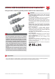
ICB12, ICB18 & ICB30 IO-Link 3-wire DC
ICB12, ICB18 & ICB30 IO-Link 3-wire DC DS EN21/05/2018
Main functions
• Integrated diagnostic function with ashing LED in the event of a short circuit or overload
• The devices can be operated in IO-Link mode once connected to an IO-Link master, or in standard I/O mode.
• In IO-Link mode the switching signals of the sensor are made available in the process data via the IO-Link interface.
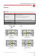
• Several sensor functions can be set via the IO-Link interface:
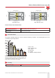
► Adjustable switching distance: 33%, 50%, 75% or 100% of the maximum switching distance.
► Adjustable hysteresis: standard or increased value.
► Divider function: the sensor gives a signal after a specied number of actuation pulses has been
reached.
► Switch-on delay: the switching pulse is generated after the sensor actuation.
► Switch-o delay: the generation of the switch signal is delayed by the set time after sensor actuation.
► Temperature error: temperature is out of specications.
► Temperature over-run and under-run: temperature is out of the limits dened by the user.
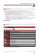
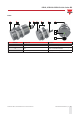
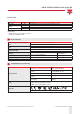
References
Order code
I C B I O
Enter the code option instead of
Code Option Description
I - Inductive sensor
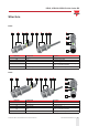
C - Cylindrical housing with threaded barrel
B - Nickel-plated brass housing
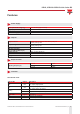
12 M12 housing
18 M18 housing
30 M30 housing
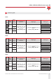
S30 Short housing with thread length of 30mm
L50 Long housing with thread length of 50mm
F Flush
N Non-ush
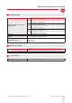
- Sensing distance [mm] E.g. 04 = 4mm; 14 = 14mm
04 or 08
ICB12 ush: 4mm
ICB12 non-ush: 8mm
08 or 14
ICB18 ush: 8mm
ICB18 non-ush: 14mm
15 or 22
ICB30 ush: 15mm
ICB30 non-ush: 22mm
M1 M12 plug
A2 2 m PVC cable
IO - IO-Link programmable version
Additional characters can be used for customized versions.