
Datasheet

7
Carlo Gavazzi Automation S.p.A.
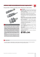
ICB12, ICB18 & ICB30 IO-Link 3-wire DC
ICB12, ICB18 & ICB30 IO-Link 3-wire DC DS EN21/05/2018
-0,040,040,120,2 0,28 0,36 0,44 0,52 0,6
-0,76
-0,38
0
0,38
0,76
-24
-16
-8
0
8
16
24
012345678910 11 12 13 14 15 16
Distance [Inches]
[Inches]
[mm]
Distance [mm]
S
T
-0,24-0,09 0,06 0,21 0,36 0,51 0,66 0,81
-1,4
-1,05
-0,7
-0,35
0
0,35
0,7
1,05
1,4
-30
-20
-10
0
10
20
30
-6 -4 -2 0246810121416182022
Distance [Inches]
[Inches]
[mm]
Distance [mm]
S
T
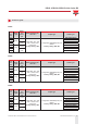
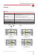
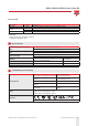
Fig. 5 M30 Flush Fig. 6 M30 Non-ush
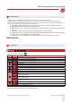
Sensors with IO-Link communication
Rated operating distance S
n
Programmable via IO-Link: 33%, 50%, 75% or 100% of the maximum S
n
Factory setting: 100% of the maximum S
n
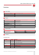
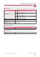
Hysteresis (H)
Programmable via IO-Link: standard or increased
Factory setting: standard
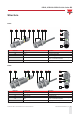
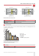
Correction factors
The specic operating distance S
n
refers to dened measuring conditions. The following data have to be
considered as general guidelines.
Fe360 : Steel
CrNi : Chrome-nickel
CuZn : Brass
Al : Aluminium
Cu : Copper
Sr : Eective operating distance
Fig. 7 The rated operating distance is reduced by
the use of metals and alloys other than Fe360. The
most important reduction factors for inductive prox-
imity sensors are shown in the gure.
Accuracy
Repeat accuracy (R) ≤ 5%