
Datasheet


Specifications are subject to change without notice (07.02.2014) 5
RM1A, RM1B
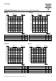
Heatsink Dimensions (load current versus ambient temperature)
RM....25
2.70 2.34 1.98 1.61 1.25 0.89
3.10 2.69 2.28 1.86 1.45 1.04
3.61 3.13 2.65 2.18 1.70 1.23
4.26 3.70 3.14 2.59 2.03 1.47
5.14 4.47 3.80 3.14 2.47 1.80
6.38 5.56 4.73 3.91 3.09 2.27
8.25 7.19 6.14 5.08 4.02 2.97
11.4 9.94 8.49 7.04 5.59 4.14
17.7 15.4 13.2 11.0 8.74 6.51
----18.2 13.6
25.0
22.5
20.0
17.5
15.0
12.5
10.0
7.5
5.0
2.5
Load
current [A]
T
hermal resistance
[
K/W]
T
A
Ambient temp. [°C]
Power
dissipation [W]
28
24
21
18
15
12
9
7
4
2
20 30 40 50 60 70
RM....50
1.03 0.86 0.70 0.53 0.37 0.20
1.27 1.09 0.90 0.71 0.52 0.33
1.54 1.32 1.10 0.89 0.67 0.45
1.85 1.59 1.34 1.08 0.82 0.57
2.26 1.95 1.65 1.34 1.03 0.72
2.85 2.47 2.08 1.70 1.32 0.94
3.73 3.24 2.75 2.26 1.77 1.27
5.22 4.54 3.86 3.19 2.51 1.83
8.21 7.16 6.11 5.05 4.00 2.95
17.2 15.0 12.9 10.7 8.51 6.33
50.0
45.0
40.0
35.0
30.0
25.0
20.0
15.0
10.0
5.0
Load
current [A]
T
hermal resistance
[
K/W]
T
A
Ambient temp. [°C]
Power
dissipation [W]
61
53
46
39
33
26
20
15
10
5
20 30 40 50 60 70
RM1.60..50
0.99 0.81 0.63 0.44 0.26 0.08
1.28 1.07 0.86 0.65 0.44 0.23
1.64 1.40 1.15 0.91 0.67 0.42
2.11 1.82 1.54 1.25 0.96 0.67
2.60 2.25 1.90 1.55 1.20 0.85
3.30 2.86 2.43 1.99 1.55 1.11
4.36 3.79 3.22 2.65 2.08 1.51
6.1 5.4 4.6 3.77 2.97 2.18
9.76 8.52 7.3 6.0 4.8 3.54
-- -- 15.47 12.85 10.24 7.6
50.0
45.0
40.0
35.0
30.0
25.0
20.0
15.0
10.0
5.0
Load
current [A]
Thermal resistance
[K/W]
T
A
Ambient temp. [°C]
Power
dissipation [W]
55
48
41
35
29
23
18
13
8
4
20 30 40 50 60 70
RM....75
Junction to ambient thermal resistance, R
th j-a
< 20.0 K/W
Junction to case thermal resistance, R
th j-c
< 0.80 K/W
Case to heatsink thermal resistance, R
th c-s
< 0.20 K/W
Maximum allowable case temperature 100 deg.C
Maximum allowable junction temperature 125 deg.C
Junction to ambient thermal resistance, R
th j-a
< 20.0 K/W
Junction to case thermal resistance, R
th j-c
< 0.50 K/W
Case to heatsink thermal resistance, R
th c-s
< 0.20 K/W
Maximum allowable case temperature 100 deg.C
Maximum allowable junction temperature 125 deg.C
Junction to ambient thermal resistance, R
th j-a
< 20.0 K/W
Junction to baseplate case thermal resistance, R
th j-c
< 0.72 K/W
Case to heatsink thermal resistance, R
th c-s
< 0.20 K/W
Maximum allowable heatsink temperature 100 deg.C
Maximum allowable junction temperature 125 deg.C
Junction to ambient thermal resistance, R
th j-a
< 20.0 K/W
Junction to case thermal resistance, R
th j-c
< 0.35 K/W
Case to heatsink thermal resistance, R
th c-s
< 0.10 K/W
Maximum allowable heatsink temperature 100 deg.C
Maximum allowable junction temperature 125 deg.C
0.91 0.78 0.65 0.52 0.39 0.26
1.10 0.96 0.81 0.66 0.51 0.36
1.34 1.17 1.00 0.83 0.66 0.49
1.60 1.40 1.20 1.00 0.80 0.60
1.93 1.68 1.44 1.20 0.96 0.72
2.38 2.08 1.78 1.49 1.19 0.89
3.06 2.68 2.30 1.91 1.53 1.15
4.21 3.68 3.16 2.63 2.10 1.58
6.51 5.70 4.88 4.07 3.26 2.44
13.5 11.77 10.09 8.41 6.73 5.04
75.0
67.5
60.0
52.5
45.0
37.5
30.0
22.5
15.0
7.5
Thermal resistance
[K/W]
Load
current [A]
Power
dissipation [W]
T
A
Ambient temp. [°C]
77
68
59
50
42
34
26
19
12
6
20 30 40 50 60 70