CARLO GAVAZZI A u t o m a t i o n C o m p o n e n t s WM23-96 Power Quality Analyzer Analizzatore di Qualità della Rete USER MANUAL MANUALE ISTRUZIONI Modular system Tecnologia modulare 877) 268-3700 · www.carlogavazzisales.
CARLO GAVAZZI A u t o m a t i o n C o m p o n e n t s ING Plug and play module system; Harmonic analysis; Wmax and PFmin storage. These are only a few among many other functions performed by your WM23-96. What’s more, Carlo Gavazzi means ISO9001 certification, a working experience of many decades and a widespread presence all over the world. All this because we want our customers to have the top service and the top products.
2 Index CARLO GAVAZZI WM23-96, Power Quality Analyzer FW rev. 01 TO BEGIN WITH . . . . . . . . . . . . . . . . . . . . . . . . . . . . . ■ Front panel description . . . . . . . . . . . . . . . . . . . ■ List and description of displayed measuring pages . . . PROGRAMMING . . . . . . . . . . . . . . . . . . . . . . . . . . . . ■ Access to the main menu . . . . . . . . . . . . . . . . . . ■ Change password . . . . . . . . . . . . . . . . . . . . . . . ■ System . . . . . . . . . . . . . . . . . . . . . . . .
3 Index ■ Front panel cut-out . . . . . . . . . . . ■ Module combination . . . . . . . . . . ■ Available modules . . . . . . . . . . . . ■ Digital input connections . . . . . . . ■ Open collector output connections ■ RS422/485 port connections . . . . ■ Elettrical connections diagrams . . TECHNICAL FEATURES . . . . . . . . . . . . . . . . . . . . . .. .. .. . . . . . . . . . . . . . . . . . . . . . . . . . . . . . . . . . . . . . . . . . . . . . . . . . . . . . . . . . . . . . . . . . . . . . .
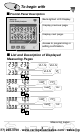
4 To begin with ■ Frontal Panel Description Back-lighted LCD Display. Display previous page. Display next page. Access to programming or setting confirmation. ■ List and Description of Displayed Measuring Pages VL1-N VL2-N VL3-N ▲ ▼ kW∑ PF∑ kvar∑ ▲ Hz ▼ kW∑ PF∑ kVA∑ Hz ▼ Measuring pages 6 ▲ ▲ ▲ V∑ 877) 268-3700 · www.carlogavazzisales.
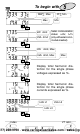
5 To begin with PF∑ Min MW∑ Max Max ▲ ▼ kW dmd kVA dmd ▲ Min Serial communication status: r=Rx; t=Tx (only with serial comm. module inserted) ▼ kW dmd, Max kVA dmd, Max ▲ Max ▼ Display total harmonic distortion for the single phase voltages expressed as %. ▲ ▼ Display total harmonic distortion for the single phase currents expressed as %. ▲ ▼ kVA L2 kVA L1 kVA L3 ▲ ▼ Index ▲ VT ratio 4 6 ▲ 3 9 877) 268-3700 · www.carlogavazzisales.
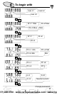
To begin with kvar L2 kvar L1 kvar L3 ▲ ▼ W L2 Max W L1 Max W L3 Max ▲ Max ▼ W L2 W L1 W L3 ▲ ▼ PF L2 Min PF L1 Min PF L3 Min ▲ ▲ ▲ Min ▼ PF L1 PF L2 PF L3 PF ∑ A L1 A L2 A L3 Neutral current ▼ ▼ Change password 4 ▲ ▲ 6 8 877) 268-3700 · www.carlogavazzisales.
Programming V L2-3 V L1-2 V L3-1 ▲ 7 V∑ ▼ Display of alarm setting (AL1 and AL2 if both alarms have been set). Display of the variable connected to the alarm. ▲ ▼ The scrolling of the measuring pages is cyclic, at the end it returns back to the first page on the left. Active alarm indicator.
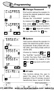
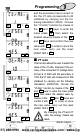
8 Programming ■ Change Password This function allows the operator to choose the desired password value (from 0 to 1000). Choose the “CnG.PASS” function S by means of the ▲ and ▼ keys, then press S to modify PASS, enter the desired value by means of the ▲ and ▼ keys and confirm ▲ S ▼ the new value with the S key. ■ System This function allows the operator to select the electrical system choosing between three-phase with neutral (3P.n) and three-phase without neutral (3P).
Programming ▲ S 1.2.. ..2.1 ▼ 9 and the secondary has a current of 5A, the CT ratio corresponds to 60 (obtained by carrying out the following calculation: 300/5). Choose the “Ct.rAtio” function by means of the ▲ and ▼ keys; to enter the S ; then select the desired value by means of the ▲ menu press S and ▼ keys and confirm the new value with S . In order to store the new value, carry out the reset ▲ ▼ S (rESEt YES S ). ■ VT ratio S ▲ S 1.2.. ..2.
10 Programming ■ Dmd calculation S S ▲ 1.2.. ..2.1 ▼ This function allows the user to select the integration time of the W, VA and var demand value (var only by means of RS485). To enter these functions select “P.int t” from the main menu by the ▲ and ▼ keys; to enter in the menu press S . Set the desired value by means of the ▲ and ▼ keys and confirm the new value with S .
Programming 11 tion are carried out as soon as the instrument is switched off. When the DIGITAL INPUT module is installed, the synchronization starts as soon as one of the digital inputs changes status (contacts 2 and 3 of the digital input module). Every subsequent change of status, resets and synchronizes again the calculation of the power dmd. It is possible to enable or disable the synchronization function managed by the digital inputs.
12 Programming ■ Digital Outputs ❑ Digital Output 1 This function enables to set the parameters of the digital outputs. Choose the “diGout” function by means of S the ▲ and ▼ keys, to enter S the menu press S .
Programming S 13 rnG: select the position of the digital point; Set-on: activation set-point, value of the variable over which the alarm is activated. Select the value of the variable by means of ▲ ▼ the ▲ and ▼ keys and con- ▲ S 1.2.. ..2.1 firm with S ; Set-oFF: deactivation set-point, value of the variable over which the alarm is deactivated. Select the value of the variable by ▼ means of the ▲ and ▼ keys S ▲ 1.2.. ..2.
14 Programming ❑ Digital Output 2 ALr: access to the alarm function (see alarm digital output on page 12) confirm with S to enter the relevant menu; rEn: enable the activation of the output by means of the serial com- S munication, confirm with enable the function.
Programming ▲ S 1.2.. ..2.1 ▼ 15 keys and confirm it with S . LoA: % value of the zero of the output range (0-20mA, 0-10V) that is generated by the minimum measured value (LoE). Select the desired value by means of the ▲ and ▼ keys and confirm it with S ▲ 1.2.. ..2.1 S ▲ 1.2.. ..2.1 ▼ S ▲ 1.2.. ..2.1 ▼ ▼ S . HiA: % value of the full scale of the output range (0-20mA, 0-10V) that is generated by the maximum measured value (HiE).
16 Programming ■ Digital Filter Select “FiLtEr” by means of the ▲ and ▼ keys: to enter the menu S press S . Select the parameters to be set with the ▲ and ▼ keys, to ▲ S 1.2.. ..2.1 enter the menu press S . There are two parameters: - rnG, to set the operating range of the digital filter. The value is expressed as % of the full scale value: set the desired value (from 0 to ▼ 100%) by means of the ▲ and ▲ S 1.2.. ..2.
Programming 17 ■ Reset of min values Select “rESEt MI” from the main menu by means of the ▲ ▼ keys, S S then confirm with S . When the instrument asks for the reset, choose, by means of the ▲ ▼ keys: “no MI” to avoid the reset or “YES MI” to confirm it. Then, press S to carry out the command. ▲ ▼ S RESET ■ Reset of max values Select “rESEt MA” from the main menu by means of the ▲ ▼ keys, S S then confirm with S .
18 Useful Information ■ How to prevent the programming by key-pad It is possible to prevent any access to programming by keypad by modifying the selector under the power supply slot (see the drawing on the left), or closing the contact number 1 of the digital input module, when present. Selector: turn the selector with a little screwdriver. - Free programming. - Lock programming.
Useful Information 19 tiples are automatically selected by the instrument according to the selected VT and CT values; • HiE: (maximum electrical scale) 100.0 K; the K and M multiples are automatically selected by the instrument according to the selected VT and CT values; • LoA: (minimum electrical scale of the analogue output) 20.
20 Useful Information ■ What is ASY The ASY variable allows the user to control the symmetry of the delta voltages (for systems without neutral) and star voltages (for systems with neutral). The variable is calculated according to the following formula: ASY= Where: Vmax - Vmin Vavg *100 Vmax is the max. value among VL1-N, VL2-N, VL3-N Vmin is the min.
Useful Information 21 ■ Alarm digital output The activation of the alarm can be UP or DOWN depending on how the ON and OFF parameters have been set, as per the following table: ON-OFF VALUES STATUS ALARM TYPE ON ≥ OFF UP ON < OFF DOWN ■ Displaying of programming menu It may be useful to know that the menus displayed by the instrument depend on its configuration; e.g.: the instrument will not display the menu relevant to the digital outputs if the optional module is not inserted.
22 Installation ■ Preliminary operations Before switching the instrument on, make sure that the power supply voltage corresponds to what is shown on the side label of the relevant module. ■ Before mounting the modules To know in which slot every module is to be mounted, refer to the figure on page 24. For a correct mounting of the instrument, insert the modules in the relevant slots, then, at the end, enter the central module, which can be a blind type module or an RS232 communication module.
23 Installation ■ Overall dimensions and panel cut-out ❑ Mounting Insert the instrument (holding its front) and fasten it (from the back) by fixing the two lateral brackets (1) (supplied with the instrument) to the appropriate location (2), using the two screws (3) supplied with the instrument. 2 1 3 Optional module connections 22 31 ▲ ▲ Useful information 21 27 877) 268-3700 · www.carlogavazzisales.
24 Installation ■ Position of the slots and relevant modules B A D C PU IM PS ■ Available modules ❑ Analogue output modules Single analogue output AO1050 (20mADC) AO1051 (10VDC) AO1052 (±5mADC) AO1053 (±10mADC) AO1054 AO1055 AO1056 AO1057 (±20mADC) (±1VDC) (±5VDC) (±10VDC) Dual analogue output AO1026 (20mADC) AO1027 (10VDC) AO1028 (±5mADC) AO1029 (±10mADC) AO1030 AO1031 AO1032 AO1033 (±20mADC) (±1VDC) (±5VDC) (±10VDC) Power supply modules 22 31 ▲ ▲ Useful information 19 26 877) 268-37
25 Installation DESCRIPTION A Single analogue output ✓ Double analogue output ✓ B C D PU PS IM Single relay output ✓ ✓ Single open coll. output ✓ ✓ Dual relay output ✓ ✓ Dual open coll.
26 Installation ❑ Digital input modules AQ1038 3 digital inputs AQ1042 3 digital inputs + aux ❑ Serial port modules AR1039 RS232 serial port AR1034 RS485 serial port ❑ Power supply modules AP1020 90-260 VAC/DC Power supply Serial port connections 22 31 ▲ ▲ Useful information 21 AP1021 18-60VAC/DC Power supply AP1025 24VAC Power supply AP1024 48VAC Power supply AP1023 115VAC Power supply AP1022 230VAC Power supply 28 877) 268-3700 · www.carlogavazzisales.
Installation 27 ■ Optional module connections ❑ Digital inputs Connection by NPN transistor. AQ1042 Digital input module Connection by PNP transistor. AQ1042 Digital input module Connection by contacts. AQ1042 Digital input module Connection by contacts. AQ1038 Digital input module ARON connections 22 31 ▲ ▲ Analogue modules 25 31 877) 268-3700 · www.carlogavazzisales.
28 Installation ❑ Relay outputs AO1058 single relay output AO1035 dual relay output ❑ Open collector outputs This diagram is valid also for the open collector modules with a lower number of outputs. The value of the load resistances (Rc) must be chosen so that the short-circuit current is lower than 100mA; the VDC voltage must be lower than or equal to 30 VDC.
Installation 29 ❑ RS485/422 serial port (AR1034) 4-wire connection. Additional devices provided with RS422/RS485 (that is RS 1,2,3...N) are connected in parallel. 2-wire connection. Additional devices provided with RS422/RS485 (that is RS 1, 2, 3 ...N) are connected in parallel. The termination of the serial output is carried out only on the last instrument of the network, by means of a jumper between (Rx+) and (T).
30 Installation ■ Electrical diagrams ❑ Single-phase connection I 1 3 5 L1 L2 L3 2 4 6 8 L1 7 N 10 L3 L2 9 U I CT connections 1 3 5 L1 L2 L3 2 4 6 8 L1 7 N 10 L3 L2 9 U L1 L1 N N CT and VT connections ❑ Three-phase, 4-wire, unbalanced load CT connections (4-wire system) CT and VT connections (4-wire system) Technical features 22 31 ▲ ▲ Modules available 25 32 877) 268-3700 · www.carlogavazzisales.
Installation CT and VT connections (3-wire system) 31 3 CT and 3 VT connections (3-wire system) ❑ ARON connection, 3-phase, 3-wire, unbalanced load CT connections (3-wire system) ARON CT and VT connections (3-wire system) ARON 22 Software functions ▲ ▲ Serial port connections 29 35 877) 268-3700 · www.carlogavazzisales.
32 Technical Features ■ Number of inputs Current: 3 Voltage: 4 ■ Accuracy (display, RS422/RS485) In=5A; Pn= In* Un UN: FS ranges AV4-5-6-7 Current: ±0.5% In +2DGT Phase-neutral voltage: ±1% Un +2DGT Phase-phase voltage: ±0.5% Un +2DGT Frequency: ±0.1% Hz Active power (@ 25°C ± 5°C, R.H. ≤ 60%): ±1% Pn +2DGT Reactive Power (@ 25°C ± 5°C, R.H. ≤ 60%): ±2% Pn +2DGT Apparent power (@ 25°C ± 5°C, R.H. ≤ 60%): ±1% Pn +2DGT Harmonic distortion: (@ 25°C ± 5°C, R.H.
Technical Features 33 ■ Input impedance AV4: 208VLL 5(6)AAC (AV4): >200 kΩ AV5: 400VLL 5(6)AAC (AV5): >900 kΩ AV6: 100VLL 5(6)AAC (AV6): >200 kΩ AV7: 660VLL 5(6)AAC (AV7): >900 kΩ ■ Frequency 50 to 60 Hz ■ Harmonic analysis Analysis principle: FFT Harmonic measurement: Current, Up to 16th harmonic Voltage: Up to 16th harmonic Type of harmonics: THD VL1, THD VL2, THD VL3, THD AL1, THD AL2, THD AL3 Display pages: THD % System: The harmonic distortion can be measured in both 3-wire or 4-wire systems.
34 Technical Features Ripple: ≤ 1% Load: 20 mADC ≤ 600 Ω; ±20 mADC ≤ 550 Ω; ±10 mADC ≤1100 Ω; ± 5 mADC ≤ 2200 Ω; 10 VDC ≥ 10 kΩ; ±10 VDC ≥10 kΩ; ± 5 VDC ≥ 10 kΩ; ± 1 VDC ≥ 10 kΩ Insulation: by means of optocouplers, 4000 VRMS output to measuring input 4000 VRMS output to power supply input. RS422/RS485 (on request). Module: AR 1034 Type: Multidrop, bidirectional (static and dynamic variables) Connections: 2 or 4 wires, max.
Technical Features 35 Controlled variables: V∑, Vn∑, PF∑, W∑, VA∑, var∑, Wdmd, VAdmd, An, ASY (asymmetry), THD V LN (the highest value among the three phases) THD A (the highest values among the three phases); On-time delay: 0 to 255s Output type: SPDT relay AC 1-8A @ 250VAC, DC 12-5A @ 24VDC, AC 15-2.5A @ 250VAC, DC 13-2.5A @ 24VDC Insulation: by means of optocouplers, 4000 VRMS output to measuring input, 4000 VRMS output to supply input; insulation between the two outputs: functional.
36 Technical Features Page 9: VA L1, VA L2, VA L3 Page 10: AL1 Page 11: AL2 Page 12: W∑, PF∑, var∑, Hz Page 13: W∑, PF∑, VA∑,Hz Page 14: W∑ (max), PF∑ (min) Page 15: W dmd, VA dmd, r.t.
Technical Features 37 Product: IEC 60688-1, EN 60688-1 Approvals: CE Connections 5(6)A: Screw-type, max 2.5 mm2 wires (2 x 1.5mm2) Housing Dimensions: 96x96x140 mm Material: ABS, NORYL, PC (front) self-extinguishing: UL 94 V-0 Protection degree: Front: IP65; Connections: IP20 Weight: Approx. 400 g (packing incl.) Nota: Some pictures have been digitally modified and may not correspond to the instrument in all its details. 32 ▲ ▲ Software functions 35 877) 268-3700 · www.carlogavazzisales.
38 User’s Page Name: . . . . . . . . . . . . . . . . . . .Surname: . . . . . . . . . . . . . Company name: . . . . . . . . . . . . . . . . . . . . . . . . . . . . . . . . WM23-96 serial number: . . . . . . . . . . . . . . . . . . . . . . . . . Password: . . . . . . . . . . . . . . . . . . . . . . . . . . . . . . . . . . . . . Instrument’s settings: CT ratio: . . . . . . . . . . . . . . . . .TV: . . . . . . . . . . System: . . . . . . . . . . . . . . . . . . . . . . . . . . . Serial address: . . . . . . .
Carlo Gavazzi GmbH Wien - AUSTRIA Carlo Gavazzi Automation Sdn Bhd Petaling Jaya, Selangor - MALAYSIA Carlo Gavazzi NV/SA Vilvoorde - BELGIUM Carlo Gavazzi BV Beverwijk - NETHERLANDS Carlo Gavazzi Inc.