CARLO GAVAZZI A u t o m a t i o n C o m p o n e n t s WM24-96 Universal Utility Meter Contatore Universale USER MANUAL MANUALE ISTRUZIONI Modular system Tecnologia modulare
CARLO GAVAZZI C o m p o n e n t s ING WM24-96: Modular Universal Utility Meter and Power Analyzer Plug and play module system; energy meters, gas and water meter. These are only a few among many other functions performed by your WM24-96. What’s more, Carlo Gavazzi means ISO9001 certification, a working experience of many decades and a widespread presence all over the world. All this because we want our customers to have the top service and the top products.
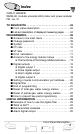
2 Index CARLO GAVAZZI WM24-96, modular universal utility meter and power analyzer FW rev. 01 TO BEGIN WITH . . . . . . . . . . . . . . . . . . . . . . . . . . . . ■ Front panel description . . . . . . . . . . . . . . . . . . ■ List and description of displayed measuring pages . . PROGRAMMING . . . . . . . . . . . . . . . . . . . . . . . . . . . ■ Access to the main menu . . . . . . . . . . . . . . . . . ■ Change password . . . . . . . . . . . . . . . . . . . . . . ■ System . . . . . . . . . . . . . . . .
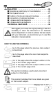
3 Index INSTALLATION . . . . . . . . . . . . . . . . . . . . . . . ■ Operations preliminary to the installation ■ Front panel cut-out . . . . . . . . . . . . . . . . ■ Position of slots and relevant modules . . ■ Connection of optional modules . . . . . . . ■ 1-phase electrical diagrams . . . . . . . . . . ■ 3-phase electrical diagrams . . . . . . . . . . TECHNICAL FEATURES . . . . . . . . . . . . . . . . . . . . . . . . . . . . . . . . . . . . . . . . . . . . . . . . . . . . . . . . . . . . . . .
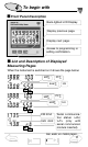
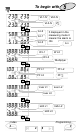
4 To begin with ■ Front Panel Description Back-lighted LCD Display. Display previous page. Display next page. Access to programming or setting confirmation. ■ List and Description of Displayed Measuring Pages When the instrument is switched on it shows the page below: PF∑ kW∑ kvar∑ ▲ Hz ▼ kW∑ PF∑ kVA∑ ▲ ▼ kW dmd kVA dmd ▼ Serial communication status: r=Rx; t=Tx (only with serial communicat. module inserted) Gas, water, en.
To begin with VL2-N VL1-N VL3-N ▲ ▼ A L2 V∑ If displayed in the measuring mode it means: the alarm is ON.
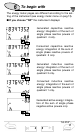
6 To begin with The energy meter pages are different according to the setting of the instrument (see energy meter menu on pag.13). ■ If you choose “tot” the instrument displays: Generated capacitive reactive energy: integration of the sum of single phase reactive powers of quadrant 4 only. ▲ ▼ Consumed capacitive reactive energy: integration of the sum of single phase reactive powers of quadrant 2 only.
To begin with 7 Consumed active energy: integration of the sum of positive single phase active powers only. ▲ ▼ ■ If you choose “tot-1.Cn” the instrument displays all the pages displayed in the “tot” selection as well as: GAS meter as m3, night tariff. ▲ ▼ GAS meter as m3, day tariff. ▲ ▼ ■ If you choose “tot-2.Cn” the instrument displays all the pages displayed in the “tot” selection as well as: Total WATER meter as m3. ▲ ▼ Total GAS meter as m3.
8 To begin with ■ If you choose “tot-Prd” the instrument displays: Reactive energy consumed during tariff 1: integration of the system active power only if positive (same is also for tariff 2, 3 and 4). ▲ ▼ Active energy consumed during tariff 1: integration of the system active power only if positive (same is for tariff 2, 3 and 4). ▲ ▼ Consumed total reactive energy: integration of the system reactive power only if positive.
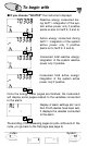
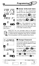
Programming 9 ■ Access to the main menu To access to the programming menus from the measuring and display phase, press the S key : when the instrument asks for the password, enter the correct PASS value S by means of the ▲ and ▼ keys; afterwards confirm by means of the S ▲ ▼ Access to the main menu S key. If the password is correct (when the instrument is new, the password is 0), the instrument goes to the main functions menu.
10 Programming ■ System This function allows the operator to select the electrical system choosing between three-phase with neutral (3P.n) and three-phase without neutral (3P). S Choose by means of ▲ and ▼ the “SySTEn” function, press S to enter the menu; then, select the desired system by means of the ▲ and ▼ keys and confirm with S . ▲ ▼ S ■ CT ratio S ▲ S 1.2.. ..2.1 ▼ This function allows the user to select the value of the CT ratio.
Programming 11 ■ VT ratio S ▲ S 1.2.. ..2.1 ▼ This function allows the user to select the value of the VT ratio. Example: if the primary of the connected VT (voltage transformer) is of 20kV and the secondary is 100V, the VT ratio will correspond to 200 (obtained by carrying out the following calculation: 20000/100). Choose the “Vt.rAtio” function by means of the ▲ and ▼ keys; to enter the menu press S , then select the desired value by means S of the ▲ and ▼ keys and con- ▲ ▼ S firm it with S .
12 Programming If, for example, you select the value “15 minutes”, the instrument calculates the demand value and updates the value every 15 minutes. See the diagram below. Where: Pc is the contractual power t1 is the selected integration period SYNCHRONIZATION OF THE POWER DEMAND CALCULATION The synchronization enables the WM24-96, by means of the digital inputs, to start the integration of the power demand at the same time as the official watthour meter.
Programming 13 ■ Access to the energy meters menu This function allows the user to choose the parameters for the management of the energy meters. Choose the function S “COUntEr” by means of the ▲ and ▼ keys: to confirm the value and enter the submenu press S . By means of S ▲ ▼ the ▲ and ▼ keys, it’s possible to scroll all the functions relating to the energy meters that will be described in detail below. ❑ The functions of the Energy Meters submenu.
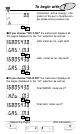
14 Programming tot 1.Cn: it enables the combination of total en. meters and day-time and nighttime GAS meters (see also “Display pages” on page 7). Press S to select “PrESCAL Cn1”, then enter by means S of the ▲ ▼ keys the weight of every pulse of the IN2 digital input of the GAS S ▲ 1.2.. ..2.1 ▼ meters and confirm with S . The same input IN2 increases alternatively the day-time and night-time GAS meters depending on the status of IN3. tot 2.
Programming 15 The increase of the Water, Gas meters, the selection of night/day tariff of the gas meters or the change of tariff (t1, t2 t3, t4) is carried out thanks to the combination of the input pulses to the AQ1038 or AQ1042 digital input module, according to the following table: SETTING RESULT DIGITAL INPUTS OF INSTRUMENT Setting “tot Prd” Display of total and partial multi-tariff energy meters. Setting “tot 1.Cn” Display of total en. meters and GAS day/night tariff. Setting “tot 2.
16 Programming ■ Digital Outputs ❑ Digital Output 1 This function enables to set the parameters of the digital outputs. Choose the “diGout” function by S means of the ▲ and ▼ keys, to S enter the menu press S .
Programming 17 The list displaying the en. meters to be retransmitted varies depending on the chosen setting of the instrument, that is, depending on the “en. meter” selection chosen among: “tot”, “tot-Prd”, “tot1.Cn”, “tot-2.Cn”, as reported in the table below: IF IF THE SELECTION IS THE SELECTION IS tot, tot-1.Cn, tot-2.Cn: tot-Prd: kWh (consumed) kWh- (generated) kvarh ind (cons. inductive) kvarh -ind (gen. inductive) kvarh CAP (cons. capacitive) kvarh -CAP (gen.
18 Programming ❑ Alarm Digital Output This function allows the user to set the parameters of the alarm digital output. Choose the “diGout1- ALr” function by means S of the ▲ ▲ ▼ S ▼ keys: to enter the menu press S . Then, set the following parameters: VAr: choose the variable to be associated to the alarm activation by means of the ▲ and ▼ keys ▲ S ▼ and confirm with S . rnG: choose the decimal point position. on: activation set-point, value of the variable over which the alarm is activated.
Programming 19 SEC: delay time from the detection of the alarm and the activation of the output. Choose the value of the delay time in seconds by means of ▲ S 1.2.. ..2.1 ▼ the ▲ and ▼ keys (up to 255 seconds) and confirm with S . Digital output 2 ❑ Digital Output 2 PUL: access to the retransmission functions of the totalized energy by means of pulses (see pulse digital output on page 16). ALr: access to alarm functions (see alarm output on page 18).
20 Programming ■ RS422/485 Serial port address Select “AddrESS” from the main menu by means of the ▲ and ▼ S keys; to enter the menu press S , then set the desired serial address value (from 1 to 255) by means of the ▲ and ▼ keys and confirm it ▲ S 1.2.. ..2.1 ▼ with S . ■ Digital Filter Select “FiLtEr” by means of the ▲ and ▼ keys: to enter the menu press S S . Select the parameters to be set with the ▲ and ▼ keys, to enter ▲ S 1.2.. ..2.1 ▼ the menu press S .
Programming 21 ■ End of programming To exit from programming and go back to the measuring mode, select “End” from the main menu by means S of the ▼ and ▲ keys, confirm it Measuring Instrument mode revision with S . ■ Reset of total meters Select “rESEt tot” from main menu by means of the ▲ S S ▼ keys, S . When the then confirm with instrument asks for the reset, choose, by means of the ▲ ▼ keys: “no” to avoid the reset or “yes” to confirm it. Then, press S to carry out the command.
22 Programming ■ Reset of partial meters Select “rESEt Prt” from the main menu by means of the ▲ S ▼ keys, then confirm with S . When the instrument asks for the reset, choose, by means of the ▲ ▼ keys: “no” to avoid the reset or “yes” to confirm it. Then, press S to carry out the command.
Useful Information 23 The variables measured by the instrument are correct if the polarities of the inputs have been observed (as shown in the figure below); if not, measuring and retransmission errors may occur due to the wrong direction of the current flowing in the primary / secondary of the connected current transformer. Example 2 “Use of digital filter”: it’s necessary to stabilize the displayed value of the VL1-N variable that varies between 222V and 228V.
24 Useful Information ■ What is ASY The ASY variable allows the user to control the symmetry of the delta voltages (for systems without neutral) and star voltages (for systems with neutral). The variable is calculated according to the following formula: ASY= Where: Vmax - Vmin Vavg *100 Vmax is the max. value among VL1-N, VL2-N, VL3-N Vmin is the min.
Useful Information 25 ■ Alarm digital output The activation of the alarm can be up or down depending on how the ON and OFF parameters have been set, as per the following table: ON-OFF VALUES STATUS ALARM TYPE ON ≥ OFF UP ON < OFF DOWN ■ Displaying of programming menu It may be useful to know that the menus displayed by the instrument depend on its configuration; e.g.: the instrument will not display the menu relevant to the digital outputs if the optional module is not inserted.
26 Installation ■ Preliminary operations Before switching the instrument on, make sure that the power supply voltage corresponds to what is shown on the side label of the relevant module. ■ Before mounting the modules To know in which slot every module is to be mounted, refer to the figure on page 28. For a correct mounting of the instrument, insert the modules in the relevant slots, then, at the end, enter the central module, which can be a blind type module or an RS232 communication module.
27 Installation ■ Overall dimensions and panel cut-out ❑ Mounting Insert the instrument (holding its front) and fasten it (from the back) by fixing the two lateral brackets (1) (supplied with the instrument) to the appropriate location (2), using the two screws (3) supplied with the instrument. 2 1 3 Optional Modules conn.
28 Installation ■ Position of the slots and relevant modules B A D C PU IM PS ■ Available modules ❑ Relay digital output modules AO1035 Dual relay output AO1058 Single relay output 26 Optional Modules 35 ▲ ▲ E.g.
29 Installation DESCRIPTION A B C D PU PS IM ✓ RS485/RS422 serial port ✓ RS232 serial port Single relay output ✓ ✓ Single open collector output ✓ ✓ Dual relay output ✓ ✓ Dual open coll.
30 Installation ❑ Digital input modules AQ1038 3 digital inputs AQ1042 3 digital inputs + aux ❑ Serial port modules AR1039 RS232 serial port AR1034 RS485/422 serial port ❑ Power supply modules AP1025 24VAC Power supply AP1024 48VAC Power supply AP1023 115VAC Power supply AP1022 AP1020 90-260 VAC/DC Power supply 230VAC Power supply AP1021 18-60VAC/DC Power supply Relay Output conn.
Installation 31 ■ Optional module connections ❑ Digital inputs Connection by NPN transistor. AQ1042 Digital input module. Connection by PNP transistor. AQ1042 Digital input module. Connection by contacts. AQ1042 Digital input module. Connection by contacts. AQ1038 Digital input module.
32 Installation ❑ Relay output AO1058 Single relay output AO1035 Dual relay output ❑ Open collector output This diagram is valid also for the single output open collector module. The value of the load resistances (Rc) must be chosen so that the shortcircuit current is lower than 100mA; the VDC voltage must be lower than or equal to 30 VDC.
Installation 33 ❑ RS485/422 (AR1034) serial port 4-wire connection. Additional devices provided with RS485/RS422 (that is RS 1,2,3...N) are connected in parallel. 2-wire connection. Additional devices provided with RS485/RS422 (that is RS 1, 2, 3 ...N) are connected in parallel. The termination of the serial output is carried out only on the last instrument of the network, by means of a jumper between (Rx+) and (T).
34 Installation ■ Electrical diagrams ❑ Single-phase connection I 1 3 5 L1 L2 L3 2 4 6 8 L1 7 N 10 L3 L2 9 U I CT connection 1 3 5 L1 L2 L3 2 4 6 8 L1 7 N 10 L3 L2 9 U L1 L1 N N CT and VT connections ❑ Three-phase, 4-wire, unbalanced load CT connection (4-wire system) CT and VT connections (4-wire system) Accuracy 26 35 ▲ ▲ Available Modules 29 36
Installation CT and VT connections (3-wire system) 35 3 CT and 3 VT connections (3-wire system) ❑ ARON connection, 3-phase, 3-wire, unbalanced load CT connection (3-wire system) ARON CT and VT connections (3-wire system) ARON Technical Features 26 ▲ ▲ Serial Connection 33 39
36 Technical Features ■ Number of inputs Current: 3; Voltage: 4 ■ Accuracy (display, RS232, RS485) In=5A; Pn= In* Un Current: 0.003Ib to 0.2Ib: ±(0.5% rdg + 3DGT); 0.2Ib to Imax: ±(0.5 rdg + 1DGT); Phase-neutral voltage: Un range: ±(0.5% rdg + 1DGT) Frequency: ±0.1% Hz Active power/energy: class 1 according to EN61036 Reactive power/energy: class 2 according to EN61268 Apparent power/energy: ±(1% Pn+2dgt), (@25°C ±5°C, R.H.
Technical Features 37 Connections: 2 or 4 wires, max. distance 1200m, termination directly on the instruments. Addresses: from 1 to 255, selectable by key-pad Protocol: MODBUS/JBUS (RTU) Data (bidirectional) Dynamic (reading only) System and phase variables: see “display pages” on page 41 All configuration parameters, activation of the static output. Data format: 1 start bit, 8-data bit, no parity,1 stop bit. Baud-rate: 9600.
38 Technical Features Alarm outputs (optional) Number of outputs: up to 2, independent Alarm type: up or down alarm, phase asymmetry Control on the variables: All variables listed in the paragraph “retransmitted variables” on page 24 can be controlled. Alarm set-point: can be modified from 0 to 100% of the displayed electrical scale. Hysteresis: From 0 to 100% of the displayed scale On-time delay: from 0 to 255 sec Relay status: selectable, normally disabled or normally enabled.
Technical Features 39 Contacts 2-3: to be used in one of the following ways: • tariff selection (t1-t2-t3-t4) and synchronization; • total meters for day-night GAS tariffs; • total GAS and WATER meters ; ■ Software functions Password: Numerical code of 4 dgts; 2 protection levels of the programming data 1st level: Password “0”, no protection 2nd level: Password from 1 to 1000, all data are protected Transformer ratio: CT from 1 to 5000 VT from 1.
40 Technical features ■ Power supply specifications 90 to 260 VDC/VAC;18 to 60VDC/VAC; 24 VAC -15%+10% 50-60Hz; 48 VAC -15%+10% 50-60Hz; 115VAC -15%+10% 50-60Hz; 230 VAC -15%+10% 50-60Hz ■ General features Operating temperature: 0 to +50°C (32 to 122°F) (H.R. < 90% non condensing) Storage temperature: -10 to +60°C (14 to 140°F) (HR. < 90% non-condensing) Installation category: Cat.
Carlo Gavazzi GmbH Wien - AUSTRIA Carlo Gavazzi Automation Sdn Bhd Petaling Jaya, Selangor - MALAYSIA Carlo Gavazzi NV/SA Vilvoorde - BELGIUM Carlo Gavazzi BV Beverwijk - NETHERLANDS Carlo Gavazzi Inc.