
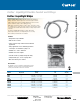
Use and Care Guide

www.tnb.com
United States
Tel: 901.252.8000
800.816.7809
Fax: 901.252.1354
Technical Services
Tel: 888.862.3289
E-514
Conduit & Fittings — Carlon
®
PVC Elbows, Conduit & Fittings
Carflex
®
Fittings Installation Instructions
• Cellular Metal Floor Raceways, Connections to Cabinets & Wall Outlets
• Class I, Div. 2, Hazardous Location
• Class II, Div. 1, Hazardous Location
• Class III, Div. 1, Hazardous Location
• Computer Room Raised Floor
• Concealed Locations
• Intrinsically Safe Systems
• Lighting Fixtures, Connection to Electric Discharge Fixture
• Non-Metallic Boxes
• RV Engine Generator
• Swimming Pool Pump Motors
• Tap Conductors (Fixture Whips)
• Underfloor Raceway, Connection to Cabinets and Wall Outlets
• Wireway, Extensions from Wireways, Wiring Methods
– Agricultural Buildings, Flexible Connections
– Electric Signs, 1000 Volts, Nominal, or Less
– Electric Signs, Over 1000 Volts (per Section 600.32(A)(1)
– Floating Buildings
– Marinas and Boatyards
– Service Entrance Conductors
• Wiring on Buildings, Outside Branch Circuits and Feeders
• Direct-Burial Applications
UL
®
Listed for Use as Indicated in Article
356 of the National Electrical Code
®
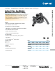
Carflex
®
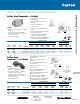
Liquidtight Conduit Technical Information
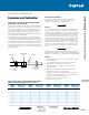
LT43C-CAR, LT43F thru J, LT20C-CAR, LT20F thru J.
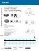
1.
Cut the end of the Carflex
®
conduit or Carflex
®
X-Flex
™
tubing square.
2
. Install compression nut and sealing gland ring over the end of the
conduit or tubing.
3.
Insert the ferrule end of the fitting into the conduit using a clockwise
twisting action.
4.
Screw fitting body into compression nut.
5.
When installation is completed, use a wrench to tighten compression
nut one-quarter (
1
⁄4) turn past hand-tight. Do not overtighten fitting.
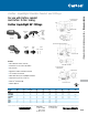
LT43D-NEW, LT43E-NEW, LT20D-NEW, LT20E-NEW.
1.
Cut the end of the Carflex
®
conduit or Carflex
®
X-Flex
™
tubing square.
2
. Install compression nut over the end of the conduit or tubing.
3.
Insert the ferrule end of the fitting into the conduit using a clockwise
twisting action. (Be sure conduit is fully inserted to the bottom of the
fitting shoulder.)
4.
Screw compression nut onto fitting body.
5.
Use a wrench to tighten compression nut one (1) full turn past
hand-tight. Do not overtighten fitting.
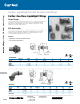
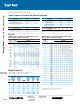
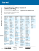
1.
There shall be no more than the equivalent of four (4) quarter (90°)
bends (360° total) between pull points, conduit bodies and boxes.
2
. The radius of the curve of the center of the conduit or tubing shall
not be less than that shown in the table (right):
*To prevent damage to conductors, conduit and fittings, do not twist Carflex during installation.
SIZE OF CONDUIT
OR TUBING
RADIUS TO CENTER OF CONDUIT
OR TUBING
INCHES (METRIC DESGR.) INCHES (MM)
3
⁄8 (14) 4 (101.6)
1
⁄2 (16) 4 (101.6)
3
⁄4 (21) 4
1
⁄2 (114.3)
1 (27) 5
3
⁄4 (146.0)
1
1
⁄4 (35) 7
1
⁄4 (184.1)
1
1
⁄2 (41) 8
1
⁄4 (209.5)
2 (53) 9
1
⁄2 (241.3)
Carflex
®
Liquidtight Flexible Conduit and Fittings