
Operator's Manual
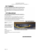
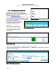


Table Of Contents
- 1. Introduction
- 2. Pre-test and System Planning
- 3. Installation
- 4. Operation and Management Center (OMC)
- 5. Appendices

PRELIMINARY RELEASE
*** This is a confidential document. Do not distribute. ***
3.3.2. Basestation Connections
Figure 16: Carlson Basestation Rear Panel
The rear panel of the Basestation has the following ports:
A. Heat Sink
B. Radio Board Ethernet Port*
C. Mini USB Diagnostic Port (Unused)
D. RF Port
E. GPS Antenna Port
F. Serial Port (Unused)
G. VGA Port (Unused)
H. USB Ports (Unused)
I. Base Controller Board Ethernet Port*
J. Ethernet Port (Internet in/out)
K. AC Power
*Base Controller Board and Radio Card Connected via Ethernet Cable
Figure 17: Carlson Basestation Ethernet Cable Connections
Page | 18