
Operator's Manual
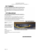
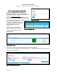


Table Of Contents
- 1. Introduction
- 2. Pre-test and System Planning
- 3. Installation
- 4. Operation and Management Center (OMC)
- 5. Appendices

PRELIMINARY RELEASE
*** This is a confidential document. Do not distribute. ***
arl
son
tative about
ect to a Basestation via a UHF
en
on is
an RF port,
3.3.4. Mounting the CPE
20)
ost
ounting
s
r unit:
re
the 10-32” nuts
3.3.3. Client Station Overview
The CPE, also call "Client
Station", is installed at the
subscriber’s premises.
RuralConnect® CPEs use
external antennas that
operate over the entire UHF
band; from 470 MHz to 698
MHz. Speak to your C
Sales Represen
the antenna selection
available.
CPEs conn
Figure 18: RuralConnect® CPE
radi
o signal. Due to the unique propagation
characteristics of signals in the UHF band,
good connections are generally possible ev
if there is a non-line-of-sight path to the
Basestation. Once a link to the Basestati
established, CPEs provide network access via
a standard Ethernet connection.
The bottom plate of the CPE has
Ethernet port and four (4) RSSI LEDs.
Figure 19: Pole-mounted CPE
CWT Enclosure
10-32x¾
Pipe Flange
Mounting Flange
Pole
10-32 Nylock
5/16" Lock Washer
5/16" Hex Nut
U-Bolt
Figure 20: CPE Mounting Bracket Diagram
Installers will use pole/wall
mounting kit (part #: 900-72
to install the RuralConnect®
CPE units (see Figure 19). M
i
nstalls will mount the unit
directly below the antenna.
The mounting bracket allows
installation using poles with a
diameter up to 2 ¼”.
Using the 900-7220 m
kit, follow the below instruction
for pole mounting the
RuralConnect® outdoo
1. Attach the mounting
flanges to the enclosu
using the 10 -32 x 3/4”
Bolts, and Nylock hex
nuts.
2. Tighten to maximum of 20 in-lbs (2.0 ft-lbs). Do not over tighten!
3. Position the enclosure on the pole.
Page | 19