
Operator's Manual
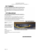


Table Of Contents
- 1. Introduction
- 2. Pre-test and System Planning
- 3. Installation
- 4. Operation and Management Center (OMC)
- 5. Appendices

PRELIMINARY RELEASE
*** This is a confidential document. Do not distribute. ***
Page | 20
4. Place the U-Bolts around the pole, and slide the pipe flanges over them with the serrated
he threads of the U-Bolts.
r the U-Bolts and secure
3.4. RuralConnect® Antenna Installation
3.4.1. RuralConnect® Antennas Available
s available for use with the RuralConnect® in
3.4.2. Basestation Antenna
#:053-470-786-6-2B-V) includes a female F-type
ations for the Omni:
-V
Connector emale 75 Ohms
t & Dimensions - 42” x 6”
3.4.3. Mounting Omni Antenna
these instructions for pole mounting the Omni antenna:
ttom section of
the
2.
le and
ith
the threads
of the V-bolts.
si
des facing the pole. See figure 1.
5. Apply an anti-seizing compound to t
6. Slide the mounting flanges (now attached to the enclosure) ove
those using the 5/16” lock washers and 5/16” hex nuts.
7. Tighten the 5/16”nuts. Do not over tighten!
The following are the only FCC-authorized antenna
the Uni
ted States. Currently, no other manufacturer produces antennas authorized for use with
the RuralConnect®. For the Base Station, you will us the Carlson Omni antenna model #053-
470-786-6-2B-V. For the Client Station, you will use the Carlson Log Periodic antenna model
#057-470-786-8-F.
The RuralConnect® Omni antenna (model
connector a
nd heavy-duty mounting bracket (part #: 920-7215) for mounting to a pole with a
diameter up to 2 ¼”.
Below are the specific
Model Number 053-470-786-6-2B
Antenna Type Omnidirectional
Beamwidth 360 degrees
Polarity Vertical
Antenna “F” type f
Frequency Range 470-786 MHz
Gain 5 dBi
Weigh 25 lbs
Using the 920-7215 mounting kit, follow
1. Attach the
mount plate to the antenna
a. Place the U-bolts around the bo
the antenna and place the mount saddles over
them the curved side facing the antenna.
b. Keeping the mount plate perpendicular to
antenna, slide the U-bolts into the mount plate
and fasten them using the 1/4” flat washers
and Nylock nuts. Do not over tighten!
Attach mount assembly to mounting pole
a. Place the V-bolts over mounting po
place the V-clamp pipe flanges onto them w
the serrated sides facing the pole.
b. Apply an anti-seizing compound to
Figure 21: Basestation Omni Antenna