
Installation manual

CarNetix CNX-P1290 V1.0 Installation Manual
Step 3. Run the Ignition Wire
After the ground connection is installed, you will need to find the “ignition” wire. This wire is
typically yellow and provides +12v when your ignition switch is on. Connect to this wire either by
splicing into it and soldering the 3 wire-ends together, or by using a “T-tap” splice connector.
You may have to search a bit for the ignition wire, but it can typically be found connected to your
radio or head-unit. It is very important that you find the correct wire since the CNX-P1290 will not
function if this wire is not connected or working properly. It would be a good idea to check, with
your DMM, that +12V is indeed present when you turn your ignition switch on, and that it goes
away when you turn it off.
Once you have located and spliced into the ignition wire, you will run this connection to the
YELLOW (pin 2) wire on the input connector (J1) of the CNX-P1290. One option (show in Figure 5
above) is to put a SPST switch in series with the ignition wire before it is connected to the CNX-
P1290. This gives you the ability to turn off the CarPC (or prevent it from turning on) regardless of
what position your ignition switch is in.
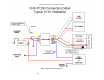
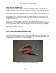
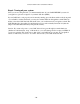
Step 4. Connect the output C134 Power Cable
The optional case power cable kit includes a power cable (Figure 3) with the appropriate plug to
insert into the existing rear-panel-mounted case power plug. This means it is not necessary to open
the case to connect power. Simply solder this power cable to the (+) RED and (-)BLACK wires on
the 6-Pin output power connector (J2) of the CNX-P1290.
Figure 6 Case Power Cable (Part of CNX-CA-C134)
- 16 -