6220 & 6240 SERIES FREEZE / THAW CHAMBER OPERATIONS MANUAL FOR MODELS 6220, 6221 6240, 6241 PO Box 715 Marietta, OH 45750 800-648-3042 740-373-6809 Fax 740-374-3760 www.caronproducts.com service@caronproducts.
Dear Valued Customer: Thank you for purchasing CARON Products & Services equipment. We appreciate your business and look forward to being your preferred supplier of controlled environment equipment products in the future. At CARON, we are committed to continuous quality improvement. Our goal is to supply our customers with highly reliable equipment at a fair price. In order to openly monitor our performance, we would appreciate your feedback on our products and services.
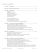
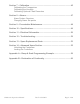
TABLE OF CONTENTS Section 1 – Warranty .................................................................................... 5 Section 2 – Equipment Overview ................................................................. 8 Section 3 – Installation ...............................................................................
Section 7 – Calibration ............................................................................... 45 Calibrating the Temperature Calibrating the Humidity Calibrating Optional Chart Recorders Section 8 – Alarms ...................................................................................... 47 Alarm System Overview Changing Alarm Set-points Section 9 – Preventative Maintenance ...................................................... 48 Section 10 – Specifications ...................................
SECTION 1- WARRANTY INFORMATION Please review this section before requesting warranty service. At CARON, one of our primary goals is to provide customers with high levels of personal service and top quality products, delivered on time, and backed by technical service and support for the life of the product. Before contacting us for warranty service, please be aware that there are repairs that are not covered under warranty. These include: 1) Calibration of control parameters.
NOT COVERED: Cost of express shipments such as Federal Express, UPS Next Day Air, UPS Second Day Air, or any other express shipment charges. Any customer modifications of this equipment, or any repairs undertaken without the prior written consent of CARON, will render this limited warranty void. CARON is not responsible for consequential, incidental or special damages. In no event will CARON be responsible for damages more than the price of the product.
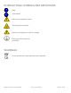
INTERNATIONAL SYMBOLS AND DEFINITIONS ? Help i Information Warning of hazardous area Warning of hot surface Warning of dangerous electric voltage Earth (ground) protective conductor WARNINGS Local government may require proper disposal 6200 series Operations Manual Rev D 2/14/2012 Page 7 of 60
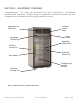
SECTION 2 – EQUIPMENT OVERVIEW Congratulations! You have just purchased the latest technology in freeze/thaw environmental chambers. Before using the equipment, familiarize yourself with key components of the product and thoroughly read this manual.
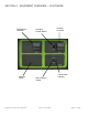
SECTION 2 – EQUIPMENT OVERVIEW -- CON TINUED Temperature Controller Options Panel 6200 series Operations Manual Humidity Enable Switch Alarm Silence Switch Rev D 2/14/2012 Humidity Controller Visual Alarm Indicator Page 9 of 60
SECTION 3 -- INSTALLATION Unpacking Your new unit has been thoroughly packaged to avoid shipping damage. However, the unit should be fully inspected upon arrival before signing for receipt. If the package has visual damage, notes should be made on the freight bill and signed by the delivery company. In the event of concealed damage after the unit is uncrated, keep the carton and packaging material.
Preliminary Cleaning Your new environmental chamber was thoroughly cleaned prior to leaving the factory. It is recommended however, to disinfect all interior surfaces with a general purpose laboratory cleaning agent prior to using the product. After cleaning, dry all interior components with a sterile cloth as necessary. Installing the Port Stoppers The unit has an access port built into each side of the cabinet.
Leveling the Unit Place a level on the middle shelf of the incubator. Adjust the feet until the unit sits level left to right and front to back. Even if the unit is level without adjustment, the leveling feet should still be lowered to avoid the cabinet moving while opening and closing the outer door & prevent a flat spot from forming on the casters. Connecting the Drain Line When using a pressurized water source, failure to connect the unit to a drain could result in facility flooding.
Use only distilled or deionized water with a resistivity between 50K-CM and 1M-CM and a pH of greater than 6.5. Using water outside this range will void your warranty. Do not use water that contains chloramines. Chloramines can damage internal rubber gaskets resulting in leaks. A water inlet fitting on the back of the unit and ¼” black tubing are provided to connect the water supply to the chamber. Connect an appropriate water supply to the fitting.
Connecting Communications & Analog Outputs This unit comes standard with features such as RS485 communications and analog outputs. A set of terminals are provided to connect to RS485 communications and analog outputs. Analog Outputs Analog outputs are either milliamps (0-20mA, 4-20mA) or voltage (0-5V, 1-5V, 0-10V, 0-20V) signal output that represents each of the displayed temperature (and humidity) values. These options can be used for connection to in-house data acquisition, recorder, or alarm system.
RS-485 communications are intended to communicate with a PC using ModBus RTU or Standard Bus. The maximum number of chambers connected to a single PC is limited to 247 controllers (Modbus) or 16 controllers (Standard Bus). Chambers 6221 & 6421 have one controller each. Chambers 6220 & 6420 have two controllers each. Connect shielded wires to the RS-485 Communications terminal blocks. Communications wires should be shielded and routed away from power wires. Maximum distance of total wire is 2000 feet.
SECTION 4 – ACCESSORY INSTALLATION Connecting Alarm Contacts (ALRM301) With the purchase of ALRM301, a set of terminals on the rear of the unit is provided to monitor temperature and humidity (6220 & 6240 only) alarms. With the alarm contacts, the terminals provided allow for a NO (normally open) output, a NC (normally closed) and COM (common) connection. In the event of an alarm condition or power failure, the NO contact will close, and the NC contact will open.
Installing Carboy Water System (BOTL301) Models 6220 & 6240 can be purchased with an optional 2.5 gallon carboy water system. The carboy system is preassembled and shipped inside the chamber. The four ¼” bolts required to mount the carboy to the unit will be mounted in the left hand side of the chamber. Remove the carboy assembly from inside the chamber and attach it to the chamber using the ¼” bolts.
Installing the Heatless Dryer Package (DRYR301) The Heatless Dryer Package extends the operational limits to a minimum humidity control point of 2% RH and improves the dehumidification rate by purging the chamber with dry air. Air flows through the Dryer Package only when dehumidification is required to maintain the humidity set point. It uses compressed air at 90 to 100 psig to operate. Maximum airflow required is 480 SCFH (8 CFM).
Incoming compressed air must be free of dirt, oil, moisture and filtered to 10 microns minimum. Incoming compressed air must not exceed 100 psig. CARON recommends installing a pressure gauge, filter, and shutoff prior to the dryer to monitor incoming air pressure. The air supply (either house air or other compressed air source) must be 90 to 100psig at the air supply inlet. An oil-less compressor may be used. A Sound Suppression Kit maybe used to reduce the dryer noise (contact CARON service for details).
3. Attach 3/8” orange tubing from the chamber to the flow meter outlet. Flow Meter Outlet 4. Connect compressed air to dryer package inlet fitting (1/4 NPT) Dryer Inlet See Operations section of the manual for instructions on setting the pressure regulator and flow meter.
Connecting the Fluorescent Lighting (LGHT301 & LGHT305) Chambers with optional fluorescent lighting have light banks consisting of two lamps each. 6220 series models have three independent light banks and 6240 series models have four light banks on two independent controls. The light banks are suspended to the shelf underside. The lights shipped fully installed in place from the factory. See the Operations or Maintenance sections of the manual for more details.
Installing Drain Water Pump (PUMP301) In applications where a floor drain is not available and a CARON water recycling system is not being used, a drain pump can be purchased to pump any excess condensate from the chamber to a local sink or drain. The pump is located near the middle of the back of the chamber. Connect the supplied tubing from the pump to the sink / drain. The tubing may be run vertically into a ceiling but should not exceed 15 feet height.
SECTION 5 – OPERATION With the chamber properly installed and the appropriate utilities connected, the power switch on the lower right of the control bezel can be turned on. Within a few minutes, the temperature and humidity will begin to approach set-points. Allow the unit to stabilize for 12 hours before use or prior to making any calibration adjustments.
Changing the Humidity Set-point (6220 & 6240 only) Actual Humidity Increase Humidity Set-point Humidity Set-point Enable Humidity Control Switch Decrease Humidity Set-point EZ Button To set the humidity set-point, press the UP arrow to increase the humidity set-point by 1% RH. Press the DOWN arrow to decrease the humidity set-point by 1% RH. Pressing and holding either button will cause the set-point to scroll rapidly in either direction.
Operation of the Defrost / Low Temperature System A Defrost System is used to maintain operational temperature below 5ºC. When the chamber temperature is below 4.5ºC, the defrost system is enabled automatically. When the chamber temperature is above 4.5ºC (except during a defrost cycle), the defrost system is disabled automatically. When the defrost system is enabled (below 4.5ºC), a defrost cycle will occur once every 96 hours and lasts for 20 minutes.
Operation of the Delux Controller System The chambers can be purchased with upgraded controllers. The controllers have additional features of RS485 communications, analog outputs, and ramp & soak. RS485 Communications: Each controller on the network (connected to the same PC or master device) must be programmed with a unique address. If multiple chambers are being connected, each controller will have to be assigned a unique address.
Analog Outputs: With DLUX301 & DLUX302 controllers, there is an analog output signal for temperature and humidity which represents the actual chamber values. This allows the chamber to be connected to an in-house data acquisition or alarm system. The analog signal outputs are selectable as either voltage DC or milliamp. In both cases, the output is scalable from 0.0 to 20.0. Common settings are 0-1V, 0-5V, 1-5V, 0-10V, 0-20mA, and 4-20mA. The factory default settings are 0-5V.
Set the Scale Low value to correspond with the minimum value of the process output in electrical units. For 0-5V, set to 0. For 1-5V, set to 1. For 4-20mA, set to 4. Set the Scale High value to correspond with the maximum value of the process output in electrical units. For 0-5V, set to 5. For 1-5V, set to 5. For 4-20mA, set to 20. Set the Range Low value to the minimum temperature (or humidity) that will correspond with the Scale Low value (default is 0.0).
Ramp & Soak: A ramp and soak control system is included with DLUX301 & DLUX302 controllers. This allows the user to store up to 40 steps spanning 4 profiles. A step consists of a change in set-point (or ramp). Another step is used to maintain a set-point for a fixed duration (or soak). Steps can also be repeated any number of times. The temperature and humidity control systems are independent. Temperature can run through a profile while humidity is maintained constant and visa versa.
SECTION 6 – ACCESSORY OPERATION Using the Carboy Water System (BOTL301) To fill the carboy while attached to the chamber, unscrew the cap. Fill carboy with distilled or deionized water (see Connecting the Water Supply section for details). The carboy holds 2.5 liters. If the carboy must be removed in order to fill it up, first disconnect the tubing between the carboy and chamber by pressing the metal lever at the tubing connects / disconnects at the bottom of the carboy.
Operation of the Heatless Dryer Package (DRYR301) The flow meter shows the flow rate of dry air entering the chamber. It is adjustable by the knob at the bottom of the meter. Maximum performance is obtained at 300 SCFH (or 5 CFM). Operating the unit above or below this purge rate may decrease performance!! A pressure regulator is installed between the tower dryers and glass flow meter to limit the pressure into the flow meter. The regulator should be set at a maximum of 100psi. 1.
Controlling the Optional Fluorescent Lights (LGHT301 & LGHT305) The diurnal chamber comes with a fluorescent lighting system used to simulate day and night testing. There are separate temperature and humidity (optional) set-points that correspond with the lights on (day) and lights off (night). The set-points can also be made the same if continuous conditions are needed throughout the light cycles. The diurnal lighting system consists of separate light banks.
Operating the timer The power switch enables and disables the lights and cycle timer. When the timer is “on”, the 2nd set-point (also known as “idle set point”) on the controllers is enabled as well as the lights. The timer will display “OUT” corresponds to lights being enabled. The timer has an adjustable “on” and “off” cycle times which repeat continuously. SET1 corresponds to the lights “on” cycle time and SET2 to the lights “off” cycle time.
Accumulate or Reset Factory default is set so the timer continues where it left off after a power cycle (accumulate). This prevents the timer from re-starting in the event of an electrical brown-out or power outage. To change the setting so the timer re-starts to zero when power is cycled, follow the steps below. A power outage will not change the cycle time (SET1 & SET2) values. 1. 2. 3. 4. Hold the MODE button down for 3 seconds The red display will show ōFtr.
Controlling the LED Lighting (LGHT302) The LED lighting system creates low-level internal lighting. There are separate temperature and humidity (optional) set-points that correspond with the lights on (day) and lights off (night). The set-points can also be made the same if continuous conditions are needed throughout the light cycles.
Operating the timer The power switch enables and disables the lights and cycle timer. When the timer is “on”, the 2nd set-point (also known as “idle set point”) on the controllers is enabled as well as the lights. The timer will display “OUT” corresponds to lights being enabled. The timer has an adjustable “on” and “off” cycle times which repeat continuously. SET1 corresponds to the lights “off” cycle time and SET2 to the lights “on” cycle time.
Examples for how to start your timer during day or night modes Night Start Procedure: 1. Set the timer to SET 1 2. Enter the length of time you would like the lights off (night setting) Example 12 Hrs. 3. Set the timer to SET 2 4. Enter the length of time you would like to have the lights on (day setting) Example 12 Hrs. 5. Determine what time you would like to have the timer change between day/night 6. Example 7:00 P.M. switch to night setting (lights off) 7. At 7:00 P.M.
Accumulate or Reset Factory default is set so the timer continues where it left off after a power cycle (accumulate). This prevents the timer from re-starting in the event of an electrical brown-out or power outage. To change the setting so the timer re-starts to zero when power is cycled, follow the steps below. A power outage will not change the cycle time (SET1 & SET2) values. 6. 7. 8. 9. Hold the MODE button down for 3 seconds The red display will show ōFtr.
Interior Electrical Outlet (OUTL301 & OUTL302) An optional interior duplex electrical outlet is available to supply power to small interior appliances such as shakers or stirrers. It is not intended to power high current draw devices. The outlet is 115V and GFI protected. For chambers that have a single interior duplex outlet, the outlet is fused at 2.0 Amps. Chambers with two interior duplex outlets are fused at 4.0 Amps total.
Operation of Front Mounted 10” Recorders (RCDR303, RCDR304) Built in 10” thermal pen recorders can be purchased with CARON chambers. The recorders are shipped installed on the outer door of the chamber from the factory and require no further installation. Unlike ink pen recorders, the thermal recorders draw their own chart and control lines. The 10” recorders have been setup at the factory in the following configuration: 7 Day / 24 Hour / Temperature 0-100°C / Humidity 0-100% (for dual input recorders).
save all of the changes that have been made to the recorder's configuration. The thermal pen arm will move off of the chart allowing you to place the recording chart paper onto the recorder. Press and release the Change Chart button to begin recording. Changing the Chart Paper: Press and hold the Change Chart button (#3) for approximately one (1) second until the pen begins to move off scale and then release the button. Note: The green LED light will flash fast while the thermal pen arm is moving off scale.
Recorder Calibration: If calibration is required for single input recorders, use the Left (#1) and Right (#2) arrow buttons on the recorder to calibrate the temperature being recorded on the chart to correspond to the temperature of the solution. The arrow buttons must be held for approximately eight (8) seconds before the pen begins to move. If calibration is required for dual input recorders, you must first select the input that you wish to calibrate.
Operation of Thermal Side Mounted Recorders (RCDR314, RCDR315) Side mounted Honeywell DR 4500 Truline Circular Chart Recorders are also available with CARON chambers. This chart recorder uses reliable microprocessor operation to generate dependable thermal traces on universal 12-inch (310 mm) charts. The twoinput models (RCDR315) accepts inputs from a temperature sensor and a humidity sensor. The single-input model (RCDR314) records temperature only.
4. Press the FUNC button and ‘CHRT SPD’ will show 5. Use the up and down arrow keys to select one of the standard settings (8 hr, 12 hr, 24 hr, 7 days) or ‘x HR’ to specify a unique speed. 6. If specifying a unique speed, press the FUNC button and use the up and down arrow keys to set the chart speed in hours (6 to 744). 7. Press the LOWR DISP button to return to the main display. 8. Press the CHART button to start recording at the new speed. 9. Close the door.
SECTION 7 – CALIBRATION The temperature and humidity systems can all be calibrated as necessary. CARON recommends an annual calibration check of each system. Before making a calibration adjustment, allow the cabinet to stabilize a minimum of 12 hours from a power off condition. If the unit has been in operation, allow a minimum of 3 hours of stable operation at all set-points.
Calibrating the Humidity If humidity calibration is needed, the following steps can be taken: Infinity Key Advance Key Locate the reference instrument’s temperature sensor in close proximity to the cabinet’s geometric center. Be sure that the stabilization times described earlier have been satisfied prior to performing this calibration. Press the advance key until the green display reads i.CAL (calibrate). Pressing the UP arrow will increase the Humidity calibration offset by 1%.
SECTION 8 – ALARMS Alarm System Overview The chamber control system is equipped with an alarm system that constantly monitors temperature, and humidity (on humidified models) to ensure the user is notified if the cabinet goes into an alarm condition. Notification occurs via a RED indicator light and an buzzer. Each alarm condition has been factory programmed to minimize nuisance alarms while maximizing warning time.
SECTION 9 – PREVENTATIVE MAINTENANCE The CARON chamber has been robustly designed to minimize performance problems. However, regular maintenance is very important for continuous trouble free operation. As a general rule, CARON recommends an annual calibration check of the temperature, and humidity systems. CARON offers a full range of on-site calibration and validation services. We also offer preventative maintenance contracts on our equipment.
SECTION 10 – SPECIFICATIONS MODEL Temperature Range 6220 6221 6240 -25°C to 70°C Temperature Control ± 0.1°C Temperature Uniformity at 20°C ± 0.
SECTION 11 – ELECTRICAL SCHEMATICS 6200 series Operations Manual Rev D 2/14/2012 Page 50 of 60
SECTION 11 – ELECTRICAL SCHEMATICS (CONTINUED) 6200 series Operations Manual Rev D 2/14/2012 Page 51 of 60
SECTION 12 – TROUBLESHOOTING Problem -- Unit will not turn on Is the unit connected to a dedicated electrical circuit as defined in the installation section of the manual? Is there power at the electric outlet the unit is plugged into? Is the unit’s power switch turned on? Problem -- Unit temperature is above / below temperature set-point Has the unit’s temperature set-point been recently lowered / raised and if so has the unit been allowed 12 hours stabilize at the new set-point? Has the inner door been re
SECTION 13 – SPARE / REPLACEMENT PARTS General Part Number MTR-130 BLW-112 BLW-114 CTR-134 POW-108 FLTR301 CRD-110 STP-101 Description Blower Motor Blower Wheel (6220 & 6221) Blower Wheel (6240 & 6241) Watlow Delux Controller 24V DC Power Supply Condenser Filter Replacement Kit Power Line Cord 2” Rubber Port Stopper Temperature Related Part Number HTR-147 RMT-114 RMT-116 RTD-101 REL-103 CMP-123 CMP-124 MTR-152 REL-152 REL-154 SOL-108 Description Air Heater 107C Air Heater Thermostat 121C Air Heater Therm
Fuse Related ID Description 230V SW1 Main circuit breaker switch CBR-116 (12A) FUS1 Front mount chart recorder fuse FUS-155 (0.08A) FUS2 Side mount chart recorder fuse FUS-156 (0.16A) FUS3* Internal outlet fuse (single duplex) FUS-151 (2A) FUS3* Internal outlet fuse (double duplex) FUS-163 (4A) FUS5* Int. outlet transformer fuse (single) FUS-164 (3A) FUS5* Int. outlet transformer fuse (double) FUS-162 (2.5A) FUS7 Condensate pump fuse FUS-157 (0.32A) FUS8 Condensate pump transformer fuse FUS-157 (0.
SECTION 14 – ADVANCED USERS SECTION Unlocking the Controllers The temperature and humidity controllers are factory programmed for precise control. Unlocking the controllers gives the user access to all parameters. Modifying parameters that are not thoroughly understood can adversely affect chamber performance that will not be covered under warranty.
APPENDIX A – RAMP & SOAK EXAMPLE General An efficient way to program a profile is to first outline what the temperature controller should do. If the chamber has humidity control, an outline should be generated for this too. Example of a temperature profile outline: Profile 1 Step 1 Step 2 Step 3 Step 4 Step 5 Step 6 Step 7 Ramp to 20ºC as quickly as possible Stay at 20ºC for 2.
9. Use the UP and DOWN arrow buttons to define each parameter and the ADVANCE button to go to the next parameter. The parameters are described below: Parameter Target set-point Hours Minutes Seconds Rate Wait for process instance Wait for process value Wait Event 1 Wait Event 2 Jump Step Jump Count End Type Off Hold User Event Output 1 Event Output 2 10. 11. 12.
Step 2 Soak step type Time in hours Time in minutes Time in seconds Event Output 1 Event Output 2 P1 S.tyP hoUr Min SEC Ent1 Ent2 2 SoAH 2 30 0 oFF oFF Step 3 Rate step type Target set-point (50ºC) Ramping rate (1ºC per minute) Event Output 1 Event Output 2 P1 S.tyP T9.SP rAtE Ent1 Ent2 3 rAtE 50 1 oFF oFF Step 4 Soak step type Time in hours Time in minutes Time in seconds Event Output 1 Event Output 2 P1 S.
Step 8 Un-used step P1 S.tyP 8 UStP Step 9 Un-used step P1 S.tyP 9 UStP Step 10 Un-used step P1 S.
DECLARATION OF CONFORMITY Caron Products and Services, Inc.