MODEL CRSY102 CONDENSATE RECIRCULATING SYSTEM OPERATIONS MANUAL PO Box 715 Marietta, OH 45750 800-648-3042 740-373-6809 Fax 740-374-3760 www.caronproducts.com service@caronproducts.
Dear Valued Customer: Thank you for purchasing CARON Products & Services equipment. We appreciate your business and look forward to being your preferred supplier of controlled environment equipment products in the future. At CARON, we are committed to continuous quality improvement. Our goal is to supply our customers with highly reliable equipment at a fair price. In order to openly monitor our performance, we would appreciate your feedback on our products and services.
WARRANTY INFORMATION EQUIPMENT LIMITED WARRANTY Please review this section before requesting warranty service. At CARON, one of our primary goals is to provide customers with high levels of personal service and top quality products, delivered on time, backed by technical service and supported for the life of the product. Before contacting us for warranty service, please be aware that there are repairs that are not covered under warranty. WARRANTY DEFINED Caron Products & Services, Inc.
This writing is a final and complete integration of the agreement between CARON and the customer. CARON makes no other warranties, express or implied, of merchantability, fitness for a particular purpose or otherwise, with respect to the goods sold under this agreement. This warranty cannot be altered unless CARON agrees to an alteration in writing and expressly stated herein shall be recognized to vary or modify this contract. Ohio Law governs this warranty.
EQUIPMENT INTERNATIONAL LIMITED WARRANTY Please review this section before requesting warranty service. At CARON, one of our primary goals is to provide customers with high levels of personal service and top quality products, delivered on time, backed by technical service and supported for the life of the product. Before contacting your distributor for warranty service, please be aware that there are repairs that are not covered under warranty. WARRANTY DEFINED Caron Products & Services, Inc.
This writing is a final and complete integration of the agreement between CARON and the customer. CARON makes no other warranties, express or implied, of merchantability, fitness for a particular purpose or otherwise, with respect to the goods sold under this agreement. This warranty cannot be altered unless CARON agrees to an alteration in writing and expressly stated herein shall be recognized to vary or modify this contract. Ohio Law governs this warranty. Caron Products & Services, Inc.
TABLE OF CONTENTS Section 1 – Equipment Overview ............................................................. 9 Section 2 – Installation ........................................................................... 11 Choosing a Location Connecting to Chamber Drain Connecting to Chamber Water Supply Connecting Electrical Power Section 3 – Recirculator Startup ............................................................ 15 Filling Reservoir Starting Recirculator Section 4 – Maintenance .......................
INTERNATIONAL SYMBOLS AND DEFINITIONS Warning of hazardous area Warning of dangerous electric voltage Earth (ground) protective conductor WARNINGS Local government may require proper disposal CRSY102 Operations Manual Rev G 1/31/2013 Page 8
SECTION 1 – EQUIPMENT OVERVIEW Congratulations! You have just purchased the latest technology in water recirculator deionization systems. This recirculator is used in conjunction with CARON environmental test chambers. The system provides continuous, clean, filtered water to the chamber’s humidity injection system, then collects and recycles the condensate that forms in the base of the chamber.
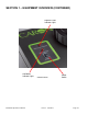
SECTION 1 – EQUIPMENT OVERVIEW (CONTINUED) Replace Filters Indicator Light Add Water Indicator Light Control Panel CRSY102 Operations Manual Rev G 1/31/2013 Power Switch Page 10
SECTION 2 -- INSTALLATION Choosing a Location Locate recirculator near the corresponding chamber(s) so recirculator inlet is physically lower than chamber drain(s). This should be a dry, clean, and level area. Locate the unit in an area out of direct sunlight and where the water level viewing window can easily be seen. The unit is on casters for easy mobility. Use the green front and black rear handles to lift the recirculator. The unit sits low to the ground and can bottom out while moving over bumps.
Connecting to Chamber Water Supply (Recirculator Outlet) Connect the chamber inlet(s) to the recirculator outlet (1/4” OD, smaller fitting connection) using the black tubing and fittings provided. Allow sufficient tubing slack so the recirculator can be moved (if necessary) and side panels accessed.
When connecting the recirculator to two chambers, use the tubing and fittings in the CRSYKIT accessory to make the appropriate connections. The water supply to both chambers should be connected with the ¼” wye fitting and ¼” OD black tubing. The water drain from both chambers should be connected with the 3/8” wye or 3/8” T fitting (whichever allows for a smoother flow of the tubing to prevent vertical rises or traps) and 3/8” blue tubing.
Connecting Electrical Power Connect recirculator to a grounded circuit. Failure to do so could result in electrical shock. Model CRSY102-1 requires a 115V, 60Hz, 5A power connection. The power cord connection is a NEMA 5-15P plug (Hubbell 5266C). Plug the power cord into the appropriate electrical outlet. Model CRSY102-4 requires a 230V, 50/60Hz, 2A power connection. The power cord connection is a CEE 7/7 plug. Plug the power cord into the appropriate electrical outlet.
SECTION 3 – RECIRCULATOR STARTUP Be sure recirculator outlet is connected before unit is turned on. As soon as the recirculator is turned on, water will begin flowing from the outlet. When adding water to the reservoir, do not spill onto recirculator. Ultra pure DI water is chemically aggressive. Do not put DI water with a resistivity above 1 MΩ-cm in the recirculator. Filling Reservoir 1. Unscrew reservoir cap. 2. Fill reservoir with water (distilled, low-grade deionized or tap).
Starting Recirculator 1. Turn recirculator power switch on. Reservoir viewing window will illuminate (blue) Replace filter indicator light (red) will blink once Internal air purging process will begin Recirculator outlet will become pressurized Internal water purification cycle will initiate (as necessary) 2. Purge air from chamber(s) water supply line (recirculator outlet) by setting the chamber(s) to high temperature and high humidity set points.
SECTION 4 – MAINTENANCE When adding water to the reservoir, do not spill onto recirculator. Refilling Reservoir The reservoir water level can be monitored through the front viewing window. Additionally, the low water indicator light will illuminate when the reservoir needs refilled. Water can be added to the reservoir while the recirculator is on. Do not use ultra-pure DI above 1 MΩ-cm.
4. Remove the filter wrench by unscrewing fastening screw. 5. Using the filter wrench, unscrew the tall filter housing. Tall Filter Housing (Contains DI Cartridge) on left side of unit Orientation of the DI cartridge is critical. Orient per instructions on DI cartridge container. Do not discard o-ring inside of filter housing.
6. Discard used DI cartridge and insert new DI cartridge into tall filter housing. O-ring DI Cartridge Filter Housing 7. Apply silicone grease to the o-ring. 8. Using the filter wrench, screw tall filter housing back in place until tight (tighten 1/8 turn after hand tight). 9. Using the filter wrench, unscrew the short filter housing. Short Filter Housing (Contains Carbon Filter) on right side of unit 10. Discard used carbon filter & insert new carbon filter into short filter housing.
Replacing Antimicrobial Stick 1. Unscrew reservoir cap. 2. Retrieve used antimicrobial stick from inside reservoir and detach from cable. 3. Insert new antimicrobial stick onto cable and place inside reservoir. 4. Screw on reservoir cap.
Before removing access panel(s), disconnect electrical power. Avoid exposure to direct or reflected germicidal ultraviolet rays. Germicidal ultraviolet rays are harmful to the eyes and skin. Replacing UV Light (optional accessory) 1. Turn off recirculator and unplug power cord. 2. If necessary, pull recirculator away from wall. 3. Remove left access panel (as viewed from front). To remove panel, pull down on the latch tabs and rotate panel outward. 4.
See separate ultraviolet light owner’s manual for specific warnings and instructions. 6. Discard used UV lamp Follow local regulations for disposing lamps. 7. Insert new UV lamp into lamp connector socket. 8. Install UV light housing cap (with attached new UV lamp) into UV light housing. 9. Re-attach ground clip. Ground clip must be securely attached to UV light housing to reduce risk of electrical shock. 10. Install left side access panels.
If recirculator is not powered on for more than three days or if it will be subjected to temperatures below freezing, the water should be drained. Draining Reservoir The recirculator’s internal reservoir can be drained by either of two ways: 1. Turn off recirculator and unplug power cord 2. Remove right side (as viewed from front) access panel 3. Locate ball valve 4. Direct ball valve flow into an empty container and open valve.
Severe Cleaning Procedure In the unlikely event that the recirculator becomes contaminated, a severe cleaning procedure may be used. This involves disconnecting the recirculator from the chamber(s) and flushing the system with bleach. (Note: If repeated occurrences of severe contamination happen, then it is recommended to add the UV light LGHT601 option to the recirculator). 1. Turn the humidity switch ‘off’ on the chamber(s) 2. Turn the CRSY102 off and unplug the electrical power cord 3.
SECTION 5 – PREVENTATIVE MAINTENANCE Before removing access panel(s), disconnect electrical power. Electrical components are located in an electrical box. Access is through the left (as viewed from front) access panel. For additional service support, contact your local distributor or CARON service department at service@caronproducts.com. If recirculator is not powered on for more than three days or if it will be subjected to temperatures below freezing, the water should be drained.
SECTION 6 – BRIEF TROUBLESHOOTING Reservoir viewing window does not illuminate (blue) Is recirculator plugged in? Is the power switch turned on? Has the recirculator circuit breaker tripped? If so, reset internal circuit breaker. Is there water in the reservoir? Add water light will be on. The recirculator must be powered on to prevent returning condensate (water from chamber) from overflowing inside the recirculator.
SECTION 7 – SPARE / REPLACEMENT PARTS Replacement Parts Part Number CRSYKIT DEM-103 FIL-607 FLTR101 HUM-113 LGT-134 TUB-132 TUB-168 GAS-114 SIL-111 WRN-102 Description Tubing & fitting kit for connection to 2 chambers DI cartridge, #20 Carbon filter, #10 Filter replacement kit for CRSY102.
SECTION 9 – ELECTRICAL SCHEMATICS CRSY102 Operations Manual Rev G 1/31/2013 Page 28
SECTION 10 – DECLARATION OF CONFORMITY CE Compliant Product Declaration of Conformity Caron Products 27640 State Route 7 Marietta, OH 45750 USA Declares that the following product: Designation: CRSY102 Model Number: CRSY102-4 Classification: Electrical Equipment for Measurement, Control, & Lab Use Rated Voltage: 220-240 V~ (ac) Rated Frequency: 50/60Hz Rated Power Consumption: 2 amps Meets the essential requirements of the following European Union Directive(s) using the relevant section(s) of the normalize