Access Bank II SNMP INSTALLATION & USER’S GUIDE 5395 Pearl Parkway Boulder, CO 80301-2490 fax 303-546-9724 http://www.carrieraccess.com Part Number 002-0097-0200 Release 2.
Copyright© 1998 Carrier Access Corporation. All rights reserved. The information presented in this manual is subject to change without notice and does not represent a commitment on the part of Carrier Access Corporation. The hardware and software described herein are furnished under a license or non-disclosure agreement. The hardware, software and manual may be used or copied only in accordance with the terms of this agreement.
FCC REQUIREMENTS FCC Requirements, Part 15 This equipment has been tested and found to comply with the limits for a Class A digital device pursuant to Part 15 of the Federal Communications Rules. These limits are designed to provide reasonable protection against harmful interference when equipment is operated in a commercial environment.
the Access Bank II - SNMP from the network until the problem is resolved. User repairs must not be made. Doing so will void your warranty. Do not install the Access Bank II - SNMP on public coin service provided by the telephone company. Connection to Party Line service is subject to state tariffs. (Contact your state public utilities commission for further information.
Users should ensure for their own protection that the electrical ground connections of the power utility, telephone lines and internal metallic water pipe system, if present, are connected together. This precaution may be particularly important in rural areas. CAUTION: Users should not attempt to make such connections themselves, but should contact the appropriate electric inspection authority, or electrician, as appropriate.” CP - 01, Part I Section 10.
of. No agent, distributor, or representative is authorized to make any warranties on behalf of CAC or to assume for CAC any other liability in connection with any of CAC’s PRODUCTS, Software, or Services. WARRANTY PRODUCT RETURNS PRODUCTS may not be returned without prior assignment of a Return Material Authorization (RMA) number from Carrier Access Corporation. Call CAC Customer Support at (800) 495-5455 or (303) 442-5455 to request an RMA number.
This manual is organized into chapters as follows: Chapter 1. Introducing the Access Bank II - SNMP Provides a general introduction to the Access Bank II - SNMP including summaries of its standard functions, features, and optional enhancements. Chapter 2. Product Description Describes the general physical characteristics and layout of the Access Bank II - SNMP, including the Control Panel, digital and analog interface connectors, power connector, DIP switches and LED status indicators. Chapter 3.
xi Table of Contents CONTENTS (Access Bank II - SNMP) Chapter 1 Introducing the Access Bank II SNMP 1-1 1.1 About This Chapter . . . . . . . . . . . . . . . . . . . . . . . . . . . . . . . . . . . . . . . . . . . . . . . . . . . . . . .1-1 1.2 General System Overview. . . . . . . . . . . . . . . . . . . . . . . . . . . . . . . . . . . . . . . . . . . . . . . . . .1-1 1.3 Features, Functions, and Options . . . . . . . . . . . . . . . . . . . . . . . . . . . . . . . . . . . . . . . . . . . .1-2 1.3.
xii 3.2.1 Total Bandwidth . . . . . . . . . . . . . . . . . . . . . . . . . . . . . . . . . . . . . . . . . . . . . . . . . . 3-2 3.2.2 DS-1 Output Signals. . . . . . . . . . . . . . . . . . . . . . . . . . . . . . . . . . . . . . . . . . . . . . . 3-2 3.3 Line Codes . . . . . . . . . . . . . . . . . . . . . . . . . . . . . . . . . . . . . . . . . . . . . . . . . . . . . . . . . . . . . 3-2 3.4 Framing . . . . . . . . . . . . . . . . . . . . . . . . . . . . . . . . . . . . . . . . . . . . . . . . . . .
xiii Table of Contents 5.1 About This Chapter . . . . . . . . . . . . . . . . . . . . . . . . . . . . . . . . . . . . . . . . . . . . . . . . . . . . . . .5-1 5.2 Installing Cables and Adapters . . . . . . . . . . . . . . . . . . . . . . . . . . . . . . . . . . . . . . . . . . . . . .5-2 5.3 Access Bank II SNMP Control Panel Interface and Power Connectors . . . . . . . . . . . . . . .5-3 5.3.1 RJ-48C Jacks for T1 Span 1 and Span 2 . . . . . . . . . . . . . . . . . . . . . . . . . . . . . . . .5-3 5.3.
xiv 7.7 Remote Monitor Screen Hierarchy . . . . . . . . . . . . . . . . . . . . . . . . . . . . . . . . . . . . . . . . . . 7-4 7.8 Initialization for Basic Operation in the Remote Mode . . . . . . . . . . . . . . . . . . . . . . . . . . . 7-4 Chapter 8 FXS-ID Configuration 8-1 8.1 About This Chapter . . . . . . . . . . . . . . . . . . . . . . . . . . . . . . . . . . . . . . . . . . . . . . . . . . . . . . 8-1 8.2 FXS-ID Voice Card . . . . . . . . . . . . . . . . . . . . . . . . . . . . . . . . . . . . .
xv Table of Contents 9.4 BRFXS/DPO Applications . . . . . . . . . . . . . . . . . . . . . . . . . . . . . . . . . . . . . . . . . . . . . . . . . 17 9.5 Setting the Transmit and Receive Levels . . . . . . . . . . . . . . . . . . . . . . . . . . . . . . . . . . . . . . 18 9.6 BRFXS/DPO Configuration Settings . . . . . . . . . . . . . . . . . . . . . . . . . . . . . . . . . . . . . . . . . 20 9.7 Setting BRFXS and DPO . . . . . . . . . . . . . . . . . . . . . . . . . . . . . . . . . . . . . . . . . . . . .
xvi 11.13.1 Call Progress LED Indicators . . . . . . . . . . . . . . . . . . . . . . . . . . . . . . . . . . . . . 11-10 11.14 E&M Normal mode cable . . . . . . . . . . . . . . . . . . . . . . . . . . . . . . . . . . . . . . . . . . . . . . 11-10 11.14.1 Description . . . . . . . . . . . . . . . . . . . . . . . . . . . . . . . . . . . . . . . . . . . . . . . . . . . 11-10 11.14.2 Cable Type . . . . . . . . . . . . . . . . . . . . . . . . . . . . . . . . . . . . . . . . . . . . . . . . . . . 11-11 11.14.
xvii Table of Contents 12.9.1 Self-Test . . . . . . . . . . . . . . . . . . . . . . . . . . . . . . . . . . . . . . . . . . . . . . . . . . . . . .12-6 12.9.2 Equipment Loopback. . . . . . . . . . . . . . . . . . . . . . . . . . . . . . . . . . . . . . . . . . . . .12-7 12.9.3 Equipment Loopback - Payload . . . . . . . . . . . . . . . . . . . . . . . . . . . . . . . . . . . .12-7 12.9.4 DS-1 Network Loopback. . . . . . . . . . . . . . . . . . . . . . . . . . . . . . . . . . . . . . . . . .12-8 12.
xviii 14.3.4 Management Information Bases. . . . . . . . . . . . . . . . . . . . . . . . . . . . . . . . . . . . . 14-4 14.3.5 Commands . . . . . . . . . . . . . . . . . . . . . . . . . . . . . . . . . . . . . . . . . . . . . . . . . . . . . 14-4 14.3.6 Statistics . . . . . . . . . . . . . . . . . . . . . . . . . . . . . . . . . . . . . . . . . . . . . . . . . . . . . . . 14-4 14.3.7 Traps. . . . . . . . . . . . . . . . . . . . . . . . . . . . . . . . . . . . . . . . . . . . . . . . . . . . . . . . . .
Table of Contents xix 14.4.4.28 trap. . . . . . . . . . . . . . . . . . . . . . . . . . . . . . . . . . . . . . . . . . . . . . . . . . .14-27 14.4.4.29 snmp . . . . . . . . . . . . . . . . . . . . . . . . . . . . . . . . . . . . . . . . . . . . . . . . .14-27 14.4.4.30 v35. . . . . . . . . . . . . . . . . . . . . . . . . . . . . . . . . . . . . . . . . . . . . . . . . . .14-28 14.4.5 Status Commands . . . . . . . . . . . . . . . . . . . . . . . . . . . . . . . . . . . . . . . . . . . . . . .14-28 14.4.
xx
About This Chapter Chapter 1 Introducing the Access Bank II SNMP Contents of This Chapter: About This Chapter .....................................1 General System Overview ..........................1 Features, Functions, and Options ................2 Standard Features ........................................2 Software Programmable Functions .............2 Auto Call Routing and Switch Functions ...2 Dual T1/CSU Network Interfaces ..............3 Digital Data Ports .......................................
3.072 Mbps of synchronous bandwidth capacity for connecting customer premises telecommunications equipment to public and private network DS1 services. An Internet or router V.35 port may be configured for up to 1.5 Mbps on one T1, while all 24 voice channels are terminated on a second T1. 1.
Digital Data Ports available for Internet connection, or for alternate routes or carriers. Doubling the bandwidth capacity of a conventional digital channel bank allows the Access Bank II SNMP to dedicate the built-in V.35 DCE data port to Internet, video, or Wide-Area Network (WAN) applications, while also performing such advanced networking tasks as Drop and Insert (D&I), and DS-0 Digital Access & Cross-connect Switching (DACS).
nections on a per channel basis from PBX office-end telephone systems to public network T1 (DS1) services using FXO terminations. The DPT feature of this card is especially useful in remote office or campus T1 environments where it can be used to support one-way Direct Inward Dialing (DID) service for voice mail and call center applications.
Local and Remote Network Management (AMI/B8ZS, D4/ESF), and to enable detection of standard D4/ESF inband loop codes by the integral CSUs. In the remote software control mode, you can use SNMP, CLI, or GUI management terminals. 1.7.2 SNMP Management The Access Bank II SNMP: • Supports Simple Network Management Protocol version 2 (SNMPv2) through its Ethernet 10Base-T port.
Agent. Normally, the Manager polls the Agent periodically to check traffic statistics. However, the Manager can also set thresholds for traps. Traps specify network events and conditions for which the Agent automatically sends a Telnet alarm message with trap data back to the Manager. 1.7.3 Command Line Interface The Access Bank II SNMP comes with a built-in Command Line Interface.
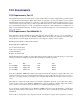
Local and Remote Network Management Remote Control Telnet in data stream V.35 Frame or IP Network T1 Access Bank II SNMP Telnet Terminal Router LAN Ethernet 10Base-T Local Control Telnet Terminal Figure 1-3: Local and Remote Telnet CLI Management For Telnet CLI management, you can use a Telnet TCP/IP communications program to access CLI through the Ethernet management port. Remote Telnet CLI operation is available using Telnet over Ethernet or using inband T1 via the V.35 data port. 1.7.
• PC Setup • Configuration • Connections • Hardware Setup • Performance Statistics • Maintenance 1.7.5 Local and Remote GUI Management For configuration, monitoring, and testing purposes, each Access Bank II SNMP is shipped with CAC’s Windows®-based GUI management software, backed by a full-featured system of contextsensitive online help.
About This Chapter Chapter 2 Product Description Contents of This Chapter: About This Chapter .................................... 1 Physical Characteristics ............................. 1 Control Panel Interface Connectors ........... 2 Control Panel DIP Switches ....................... 3 LED Test and Status Indicators ................. 3 2.
Controller card. The Controller card measures approximately 4 inches by 16.25 inches and functions as a Line Interface Unit (LIU) that integrates the two Channel Service Units (CSUs), the ringing generator, the ringback tone generator, and power converter functions. Separate Dual T1 and SNMP daughter cards measuring 1.75 inches by 6.25 inches are each mounted on the Controller card using support standoffs, plastic washers and screws.
Control Panel DIP Switches • Three-position DC power terminal input for connection to the 115 Vac to -48 Vdc Power Converter Cube, or to a customer-supplied external -48 Vdc battery power source. • Tip & Ring Analog Interface equipped with standard 25-pair Telephony Connector (female) for connection to key systems, facsimile devices, modems and PBXs. The ABII Control Panel is equipped with an interface connector for accessing the embedded SNMP agent. 2.
V.35 STATUS LED STATE OFF GREEN FLASHING GREEN RED YELLOW FLASHING YELLOW MEANING No T1 channels assigned to V.35 port CD and RTS active. T1 channels assigned and operable V.35 in loopback to equipment CD is inactive because assigned T1 is inoperable CD active RTS inactive V.
About This Chapter Chapter 3 Technical Specifications Contents of This Chapter: About This Chapter .................................... 1 Dual T1 Network Line Interfaces .............. 1 Line Codes ................................................ 2 Framing ..................................................... 2 Clock Source ............................................ 2 T1-to-T1 Delay .......................................... 2 T1 Channel Service Units (CSUs) ............ 2 Digital Data Ports ...........
3.2 Dual T1 Network Line Interfaces 3.2.1 Total Bandwidth • 3.072 Mbps 3.2.2 DS-1 Output Signals • Pulse amplitude: 2.0 V to 3.6 V ±60 Hz variations • Line Rate: 1.544 Mbps ±50 bps • Format: T1 type bipolar (except where intentional BPVs are introduced by B8ZS line coding) 3.3 Line Codes • AMI or B8ZS and line code conversions between T1 lines 3.4 Framing • D4 (Superframe) or ESF and framing format conversions between T1 lines 3.
Digital Data Ports • Standard inband and out-of-band CSU network loopbacks • Internal BER tester with selectable industry standard QRSS test patterns 3.8 Digital Data Ports 3.8.1 V.35 Serial Port • Synchronous V.35 data from 56 Kbps to 1.536 Mbps in Nx56 Kbps or Nx64 Kbps steps, all rates. • Built-in V.54 loopback code generation and detection for BERT 3.8.2 RS-232 Remote Management/Data Port • Asynchronous point-to-point RS-232 data at 9.6, 19.2, 28.8, 38.4, and 57.
defined signaling options.
Alarms Access Bank II - SNMP purchase. • Control Panel T1 test switches and status LEDs • Rear panel voice channel option switches, test switches, and status LEDs • Embedded SNMP agent for performance monitoring and configuration of T1, V.35, and RS-232 data ports 3.
• Bellcore TR-NWT-000499 Generic Transport Requirements • FCC Part 15, Class A for Radiated Emissions Control • FCC Part 68, CS-03 for T1 CSU Interface, Network Protection, Line Balance, REN • National Electrical Code 1996 Safety Requirements • NRTL Safety Listed: UL 1459, 2nd Edition concerning Minimum 600 Vrms Lightning Protection, CSA • IEEE 802.3 10baseT interface • EIA RS-232-D • RFC 1213, 1573, 1406, 1659 3.
Installation 3.
3-8 9/24/01
About This Chapter Chapter 4 Physical Installation Contents of This Chapter: About This Chapter .................................... 1 Installation Check List ................................ 1 Chassis Mounting ...................................... 5 Wall Mounting ............................................ 6 Rack Mounting ........................................... 6 Surface Mounting ....................................... 7 Mounting the Power Converter .................. 7 4.
order) with 0, 1, or 2 analog interface cards, Access Bank II - SNMP Remote Monitor software for the PC, and a power conversion cube. The package also contains one modular Category 5 T1 network interface cable, a 25-pin local management cable, a 25-pin to 25-pin null modem adapter, a 25-pin to 9-pin straight adapter, and “rabbit ear” adapter brackets with screws for wall or 19-inch rack-mounting. You will also find enclosed a copy of this manual along with a product warranty registration card.
Chassis Mounting Dual RS-232 data and magagement cable (10 ft) for connection to a router, computer, statistical multiplexer, SNA cluster controller, or SCADA equipment. This cable supports both synchronous operation at 56 or 64 Kbps, and asynchronous operation at 9.6, 19.2, 28.8, 38.4, and 57.6 Kbps. V.35 data cable - 10 ft V.35 data cable - 25 ft V.
! Caution: If the operating temperature rises above the 40 º C limit an internal thermal protection device will shut off the Access Bank II - SNMP. When the temperature is reduced below this threshold, the Access Bank II - SNMP restarts. • An installation site below 10,000 feet (3,048 m). • For operation outside these ranges, the Access Bank II - SNMP must be placed in an environmentally controlled enclosure.
Surface Mounting 4.5.1 Rack Mounting with Brackets Shipped with Unit To mount the Access Bank II - SNMP in a standard EIA 19-inch Telco equipment rack using the included adapter brackets: 1. Remove the two front adapter brackets, rotate them 90 degrees and re-attach the brackets so they face toward the unit back plate (Figure 4-2). This creates a standard five-inch offset mounting typical of telecommunications equipment. 2.
4.7 Mounting the Power Converter The Access Bank II - SNMP is normally shipped for US operation with a 115 Vac to -48 Vdc power conversion cube. This cube includes both a 5-foot grounded AC power cord and a 8-foot three-position DC power cable. The Power Converter Cube has four mounting holes for attaching the unit to a wall or other flat surface.
Mounting the Power Converter CAUTION: Do not use the rear m ounting position to m ount the unit exc ept to a sec ond rail for additional support. 1. Rem ove, rotate, and re-attach the two front m ounting brac kets as shown. 2. Mount the unit to the rac k with four sc rews.
1. Rem ove the small brac kets from the unit. 2. Fasten heavy-duty brac kets to unit as shown. 19" Heavy-duty mounting brackets CAC PN 004-0041 3. Mount the unit on the standard rack using four 10-32 x 3/4" machine screws. 4. Adjust the offset by sliding the screws in the brac ket slots, then tighten the sc rews. NOTE: To m ount units in standard EIA 23" rac ks, use heavy-duty brac ket CAC PN 004-0113.
Mounting the Power Converter 2.8" Part Number 0040113 23" Rack Mounting Bracket " 15 Part Number 0040041 19" Rack Mounting Bracket 2.
4-10 9/24/01
About This Chapter Chapter 5 Electrical Installation Contents of This Chapter: About This Chapter .................................... 1 .Installing Cables and Adapters ................. 2 Interface and Power Connectors ............... 4 Connecting the Voice Circuits .................... 5 Connecting the Dual T1 Lines ................... 6 V.35 DCE Data Port Connections .............. 7 RS-232 Management ............................... 12 Connecting the Power and Ground ......... 15 5.
5.2 Installing Cables and Adapters After mounting the Access Bank II SNMP chassis and power converter, the next step is connecting the various voice and data interfaces and the power connector using the standard and optional cables and adapters listed below in Table 5-1. Table 5-1 shows where the various T1, V.35 and RS-232 interface and power connector are located on the Access Bank II SNMP front Control Panel.
Access Bank II SNMP Control Panel Interface and Power Connectors 005-0009DCEMM-25’ 25 foot, 7.62 m 005-0010DCEMM-50’ 50 foot, 15.24 m Twenty-five-foot V.35 Data Cable for connecting a router or other digital device to a T1 network using the Access Bank II SNMP’s V.35 DCE data port, accommodating high-speed transfers up to 1.536 Mbps. This cable is optional and must be ordered separately. Fifty-foot V.
5.3.5 Tip & Ring Jack (female) Tip & Ring connections are made at this connector with an standard 25-pair telephone cable, which also connects to the punch-down block or RJ-11 “Harmonica.” Note: 4-wire E&M 12-channel voice card requires optional cables to connect to the punch-down block. These cables eliminate the use of the front panel RJ-21X Tip & Ring telephone connector. 5.
Connecting the Dual T1 Lines Table 5-2: 50-Pin Tip & Ring Jack Pair 1 2 ↓ 24 25 Pin Location 26 1 27 2 ↓ 49 24 50 25 Function Tip Channel 1 Ring Channel 1 Tip Channel 2 Ring Channel 2 ↓ Tip Channel 24 Ring Channel 24 Alarm Tip Channel 25 Alarm Ring Channel 25 5.5 Connecting the Dual T1 Lines 5.5.
5.5.2 ABAM 600 T1 Cable Table 5-4 defines the characteristics of shielded 22 AWG ABAM 600 T1 cable. Shielded ABAM 600 has better transmission characteristics and less potential for harmful crosstalk than unshielded 24 AWG twisted-pair telephone cable. Table 5-4: ABAM 600 T1 Cable Specifications ABAM 600 Cable Nominal impedance Insertion loss Far-end crosstalk Near-end crosstalk Signal wires Drain wires Shields Cable Characteristics 100 Ω +/- 5% at 772 kHz. Better than 7 dB per 1000 feet at 1.544 MHz.
V.35 DCE Data Port Connections This cable is used to connect the Access Bank II SNMP V.35 DCE data port (Figure 5-3) to synchronous V.35 DTE data sources up to 1.536 Mbps, all rates (1-24) Nx56 or Nx64 channel-rate progression. The CAC V.35 Data Cables are built according to the pin assignments listed below in Table 5-5. Figure 5-4 shows the pin layout of the standard 34-pin V.35 Winchester connector typically used to connect to Routers and FRADs. To connect the CAC V.35 data cable to the V.
TXA TXB RXA RXB ± .55 V balanced RCLKA RCLKB TCLKA TCLKB Available supply ± 5V CD RTS DTR ± 12 V single-ended CTS DSR AMP213300-3 Access Nodal Switch Cable 10, 25, or 50 ft. Fine Pitch D-Sub-26 Male Figure 5-2: Access Bank II SNMP V.
V.35 DCE Data Port Connections CHASSIS 1 14 TXB (103) (103) TXA 2 15 RCLKA (115) (104) RXA 3 16 RXB (104) (105) VRTS 4 17 RCLKB (115) (106) VCTS 5 18 (107 VDSR 6 19 20 VDTR (108/2) 7 (109) VCD 8 21 22 LLB (141) 9 (114) TCLKA 10 23 TOLKB (114) (113) EXCLKA 11 24 EXCLKB (113) (142) TM 12 25 RDL (140) 13 26 Figure 5-3: Access Bank II SNMP V.
5.7 RS-232 Management 5.7.1 RS-232 DCE Management Cable Note: The Dual RS-232 DCE Data and Management Cable (P/N 005-0001) is an optional accessory, and can be purchased from distributors and dealers of CAC products. 5.7.2 Local Management Cable To perform local or remote management and performance monitoring using the Command Line Interface or MS Windows-based Remote Monitor software installed in a local PC or laptop computer requires using the CAC 25-Pin Local Management Cable (P/N 005-0003).
RS-232 Management Table 5-6: CAC Local Management Adapter Cable Pin Assignments Designation Shield Ground Secondary TXD Secondary RXD Secondary RTS Secondary CTS Secondary DTR Secondary CD DCE-DB25 (female) 1+ (shield) 7 2 3 4 5 20 8 D-Sub-26 (male) 1+ (shield) 7 14 16 19 13 10 12 Paired Signals (Not required) ° ° ° 5.7.
Table 5-7: Null Modem Adapter Pin Assignments Designation DCE DB25 (male) DTE DB25 (male) Shield Ground Secondary TXD Secondary RXD Secondary RTS Secondary CTS Secondary DTR Secondary CD 1+ (Shield) 7 3 2 5 4 8 20 1+ (Shield) 7 2 3 4 5 20 8 Paired Signals (Not required) ° ° ° 5.7.
Connecting the Power and Ground Table 5-8: CAC Straight Adapter Pin Assignments Designation DCE DB9 female DCE DB25 male Shield Ground Secondary TXD Secondary RXD Secondary RTS + (Shield) 5 3 2 7 6 4 8 1 9 Secondary DTR Secondary CD 1+ (Shield) 7 2 3 4 6 20 5 8 22 Pair Signals (Not required) ° ° ° ° 5.8 Connecting the Power and Ground 5.8.1 DC Power Connector Input ! Warning: Connect only -48 Vdc power to the DC input connector.
5-14 9/24/01
About This Chapter Chapter 6 Initialization and Basic Configuration Contents of This Chapter: About This Chapter .................................... 1 Connecting to the Acces Bank ................... 1 Configuring the Access Bank ..................... 2 6.1 About This Chapter This chapter describes how to initialize and configure the Access Bank II - SNMP for first time basic operation in Local mode. 6.
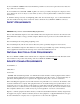
RS-232 Key System Unit Management Station FXS ABII SNMP Service Provider T1 V.35 10baseT SNMP Access Router T1 Þ ESF/B8ZS 0 24 12 LAN PC PC 768 Data to V.35 12 FXS Voice Channels Figure 6-1: The AB-II SNMP in an Example Network 6.3 Configuring the Access Bank 1. Start the system and connect the terminal. The system displays: Booting... Configuring to restored configuration...
Configuring the Access Bank Access Bank II Version 1.01 Management Version 1.29 Password: 3. Enter the password (default is cac), and press . Password: cac Password accepted Access Bank II Access Bank II/SNMP Slot --------LIU FX#1 FX#2 Card --------ABII FXS12 --- Revision --------1.23 3.03 --- Span --------1) d1 2) d2 3) f1 4) f2 Name ---------------------------------"" "T1 #2" "FX #1" "FX #2" 4.
Access Bank II> date 01/15/98 Access Bank II> date - System Time 13:27:10 01/15/1998 6. Check the time information: Access Bank II> time - System Time is 13:27:08 01/15/1998 • To correct the time (example is 5:20 PM): Access Bank II> time 17:20:00 Access Bank II> time - System Time is 17:20:05 01/15/1998 7.
Configuring the Access Bank 8.
_____ _____ _____ _____ _____ _____ _____ _____ _____ _____ _____ _____ _____ _____ _____ _____ _____ _____ _____ _____ _____ _____ _____ _____ 3) Span f1[FXS12]: "FXS Channels to KSU" d1:13 d1:14 d1:15 d1:16 d1:17 d1:18 d1:19 d1:20 d1:21 d1:22 d1:23 d1:24 4) Span f2[---]: "Analog Slot 2 - Not in Service" _____ _____ _____ _____ _____ _____ _____ _____ _____ _____ _____ _____ • To check the configuration of the V.35 port: Access Bank II> v35 - V.35 v1 (768000 bps) v35 v1 circuitid "V.
Configuring the Access Bank Access Bank II> snmp contact "George Abbot, 203-345-8897, PIN #33345" Access Bank II> snmp on Access Bank II> snmp - SNMP Group - Access Bank II/SNMP snmp name "Voice and Data Access Multiplexor" snmp location "East Georgetown" snmp contact "Nicholas Jones, 203-555-8897, PIN #33345" 9. IMPORTANT: Save the configuration, and exit the command line interface: Caution: When you complete the following sequence, do not press the key.
6-8 9/24/01
About This Chapter Chapter 7 Remote Monitor Contents of This Chapter: About This Chapter .................................... 1 Remote Monitor Software Program ........... 2 Overview .................................................... 2 Message Traffic ......................................... 3 Online Help ................................................ 3 Hardware Requirements ............................ 3 Installation ..................................................
itor User’s Guide. 7.2 Remote Monitor Software Program 7.2.1 Overview The Access Bank Remote Monitor software interface is used to configure and manage the Access Bank via the RS-232 Management Port. Installed on a local IBM-compatible PC or laptop connected to the RS-232 Management port, Remote Monitor provides a convenient user-friendly software interface for configuring, monitoring, and testing the performance of the Access Bank.
Online Help Access Bank: configuration traffic between the PC and the Access Bank, status traffic from the Access Bank to the PC, and alarm report messages from the Access Bank to the PC. The X-modem protocol is used to send/receive data from the Access Bank. A low-priority process resides in the Access Bank to process the X-modem packets and update the internal data structures accordingly.
3. The install wizard should execute and be displayed on the screen. 4. Select the location defaults and insert the appropriate diskettes when prompted. 7.7 Remote Monitor Screen Hierarchy The Remote Monitor software interface consists of a hierarchy of screens or windows. The following figure presents a simplified functional block diagram of this screen hierarchy.
Chapter 8 FXS-ID Configuration Contents of This Chapter: About This Chapter .................................... 1 FXS-ID Voice Card .................................... 1 Signaling Types ......................................... 2 FXO Switch to AB2 FXS A/B Signaling ..... 2 Wink-Start to Loop-Start or Ground-Start .. 2 Wink Delay ................................................. 3 Setting the Transmit and Receive Levels .. 3 Setting the Signaling Options ....................
FXS-ID Configuration plate of the FXS-ID card has 12 channel status LEDs and one 4-position DIP switch for selecting from a number of different signaling types. Furthermore, the back plate also contains 12 test switches that can be used to “busy out” each channel individually. On the FXS-ID card itself, each individual channel has a 6-position DIP switch for setting transmit and receive line attenuation.
Setting the FXS Transmit and Receive Levels 8.3.3 Wink Delay Select Wink Delay to translate two-state wink-start signaling toward the T1 network to an FXS ringing with delayed wink for proceed-to-send digit indication. Upon detection of an incoming seizure from the T1 network, the AB2 applies ringing voltage to the FXS channel.
FXS-ID Configuration If your FXS voice channels require different attenuation level settings than the factory defaults, proceed as follows: 1. Release the two thumbscrews on the AB2 back plate and remove the plate (see Figure 8-2). 2. To remove the FXS-ID slide-in voice card, pull out the two card ejector latches simultaneously to release the card from the internal connector, then slide the card carefully out from the rear of the AB2 chassis (see Figure 8-2). 3.
Setting the FXS Transmit and Receive Levels Figure 8-2: Accessing the FXS-ID Cards Table 8-2: FXS Signaling Summary Option Number Switch A Switch B Switch C Signaling Option 0 OFF OFF OFF 1 ON OFF OFF 2 OFF ON OFF 3 ON ON OFF Normal FXS A&B signaling for loopstart or ground-start; automatic selection based on carrier signal. FXS-ID card default. E&M wink-start-to-loop-start conversion with ringback to T1 line and calling party disconnect (Megacom, Notes 1 and 2).
FXS-ID Configuration 4 OFF OFF ON E&M immediate-start-to-ground-start conversion with ringback to T1 line (Megacom, Note 1). 5 ON OFF ON Wink-start-to-loop-start conversion with ANI/DNIS with 800 ms wink delay and calling party disconnect (Notes 1, 2 and 3). 6 OFF ON ON Wink-start-to-ground-start conversion with ANI/DNIS with 800 ms wink delay (Notes 1 and 3). 7 ON ON ON Custom Signaling Options. Please contact Carrier Access Corporation for specific details (Note 4).
FXS Signaling Option Descriptions Signaling Options & Busy/Idle Signaling Options & Busy/Idle Figure 8-3: FXS Signaling Options 8.6 FXS Signaling Option Descriptions 8.6.1 Option Switches A, B, and C Signaling options selected by the A, B, and C option switches are discussed below according to the numbered sequence from 0 to 7 in Table 8-2. 8.6.1.1 Option 0.
FXS-ID Configuration informs the equipment to hang up. 8.6.1.3 Option 2. Wink-Start to Ground-Start Conversion Switch A OFF Switch B ON Switch C OFF POTS Interface This option provides a POTS (Plain Old Telephone Service) ground-start interface between the Access Bank II - SNMP and the PBX or other phone equipment. This avoids both-way call collisions (“glare”) on PBX trunks and gives the PBX a disconnect signal when the far-end party hangs up.
FXS Signaling Option Descriptions 8.6.1.6 Option 5. Wink-Start to Loop-Start Conversion with ANI/DNIS and Calling Party Disconnect Switch A ON Switch B OFF Switch C ON This option provides a loop-start interface between the AB2 and the PBX for voice mail/phone applications. E&M wink-start signaling and per-channel ringback tones are sent to the T1 line. Ringing voltage is applied immediately after incoming seizure.
FXS-ID Configuration ! Caution: If you use this setting when no customized signaling has been installed, all back plate LEDs turn a steady RED and normal operation of the FXS-ID voice card is interrupted. Upon request, Carrier Access will provide customized FX signaling options that can include any of the aforementioned options plus others, including answer supervision wink signaling.
FXS Voice Channel Monitoring and Testing The channel test switches on the FXS-ID back plate can be used to send a 4 second continuous ringing voltage to the tip and ring pair of each FXS voice channel. You can check the operation of an individual voice channel by attaching a test telephone to the Tip and Ring pair of a particular channel at the punchdown block or RJ-11 Harmonica, then switching ON the appropriate channel test switch to test that channel.
FXS-ID Configuration 8.7.3 “Busying Out” Individual FXS Channels Switching a channel test switch to the ON position has three results on the selected FXS channel: 1. To confirm individual channel circuit integrity, 4 seconds of ringing voltage are sent to the Tip and Ring pair. The Tip is then grounded until the channel test switch is turned to the OFF position (to the right).
FXS Voice Channel Monitoring and Testing Warning: The four-second applied ring voltage (85V) can constitute a dangerous shock hazard, and can damage attached low-impedance equipment.
FXS-ID Configuration 8-14 9/24/01
Chapter 9 Battery Reversal FXS & Dial Pulse Origination Card Contents of This Chapter: About This Chapter .................................... 1 Description of the BRFXS/DPO Card ........ 2 Overview of Operation ............................... 2 BRFXS/DPO Applications .......................... 3 Setting the Transmit and Receive Levels .. 4 Battery Reversal FXS Loop-Start .............. 8 Dial Pulse Origination (DPO) .....................
Battery Reversal FXS & Dial Pulse Origination Card provides twelve 2-wire CPE analog loop-start connections to the digital T1 line using the same method used by the FXS voice card, only with the addition of Tip/Ring battery reversal. The FXS interface reverses the polarity of the battery feed towards the customer premise equipment (CPE) in response to the signaling bits coming from the T1 line.
BRFXS/DPO Applications Note: During a two-way call, the CPE -loop battery is reversed. To disconnect the call either the CPE loop current ceases or the network sends A/B bits = 0/0. The reversed state of the CPE loop, however, will be maintained until the network terminates (releases) the call. 9.
Battery Reversal FXS & Dial Pulse Origination Card Direct Inward Dial (DID) DID Lines Remote LEC Switch DID Lines DPO* Leased T1 PBX DPT* * Use CAC's FXO/DPT 12-Channel voice card Called Party's Direct Extension Figure 9-2: Dial Pulse Origination (DPO) for DID Transport 9.
Setting the Transmit and Receive Levels BRFXS V x.x 6 5 4 3 2 1 XMT RCV ON UP (ON) 4 3 2 1 4 3 2 1 4 3 2 1 4 3 2 1 UP (ON) ON 1 2 3 RCV 4 5 6 XMT Figure 9-3: BRFXS/DPO Transmit and Receive Level Options If your voice channels require different attenuation level settings than the factory defaults, proceed as follows: ! Caution: Use proper electrostatic discharge (ESD) procedures when removing and handling the analog cards. 1.
Battery Reversal FXS & Dial Pulse Origination Card 5. Press both card ejector latches in towards the FXS card to seat the 64-pin DIN connector in the matching connector on the internal Controller card. 6. Replace the back plate and tighten the thumbscrews. 9.6 BRFXS/DPO Configuration Settings The configuration of the Battery Reversal FXS/DPO card is set by a 4-position DIP switch and 12 individual channel test switches accessed through the ABI back plate.
BRFXS/DPO Configuration Settings Table 9-3 Test 24 Test 23 Test 22 Test 21 Channel Test Switches & Indicators Channels 21-24 Channel 24 Channel 23 Channel 22 Channel 21 Test 20 Test 19 Test 18 Test 17 Channel Test Switches & Indicators Channels 17-20 BRFXS/DPO Back Plate Switches Switch Function Channel Test (12 per card) Applies reverse battery to CPE loop and forces A/B bits sent toward network to 1/1 TP Busy/Idle (One per card) Selects reverse (busy) or forward (idle) battery on tipground relay
Battery Reversal FXS & Dial Pulse Origination Card 9.7 Setting BRFXS and DPO 9.7.1 Battery Reversal FXS Loop-Start The BRFXS/DPO card includes a setting for 2-wire FXS loop-start operation with battery reversal. To enable this option, set Switch A on the 4-position DIP switch to ON so that cadenced ringing voltage is applied to the CPE loop during an incoming call (See Table 9-2). The battery is reversed during this time.
Self Test Loopbacks ! Danger: Four seconds of continuous ringing voltage (85 V) will be present at the Tip and Ring pair of the channel-under-test until the test telephone is picked up to trip the ringing. Requirement: A test telephone connected to the punch down block or RJ-11 Harmonica should ring for 4 seconds. 3. As an aid to network technicians troubleshooting audio problems, 4 seconds of continuous ringback tone are also sent toward the T1 network. 4.
Battery Reversal FXS & Dial Pulse Origination Card 9-24 9/24/01
Chapter 10 12-Channel FXO & Dial Pulse Termination Card Contents of This Chapter: About This Chapter .................................... 1 Description of the FXO Card ...................... 1 Termination Options .................................. 2 Foreign Exchange Office Termination ....... 2 Dial Pulse Termination (DPT) .................... 3 Channel Attenuation Options ..................... 4 10.
12-Channel FXO & Dial Pulse Termination Card FXO or DPT termination. Also on the card, each individual channel has a two position switch for the selection of ground start or loop start (see Figure 9-3) and a 6-section DIP switch to control the line attenuation (see Channel Attenuation Options). 10.3 Termination Options The FXO/DPT card can be configured for use as either an FXO or DPT interface card. Further, FXO offers both ground start (GS) and loop start (LS) modes of operation.
Termination Options Incoming PBX FXO T1 FXS CO Outgoing Telephone Telephone Fax Fax Figure 10-1: FXO Operation ________________________________________________________________________________ Direct Inward Dialing (DID) PBX CO T1 *Battery Reversal FXS/DPO 12Channel Analog Card Calling Party Called Party's Direct Extension Figure 10-2: DPT Operation 10.3.2 Dial Pulse Termination (DPT) In DPT mode, the FXO/DPT offers near end termination for one-way Direct Inward Dial (DID).
12-Channel FXO & Dial Pulse Termination Card • detect battery reversal from the PBX for call progress and confirmation of call completion. 10.3.3 Channel Attenuation Options Each of the 12 channels can be configured to attenuate both the transmit and receive audio signal. Each channel has a 6-position dip switch; three positions for transmit attenuation and three positions for receive attenuation.
Termination Options These switches are set for -9 dB attenuation for both transmit and receive 6 5 4 FXO V x.x XMT Channel 12 is in Loop Start Mode GS 3 2 1 RCV ON LS In DPT Mode, all channels must be set for LOOP start FXO V-2.
12-Channel FXO & Dial Pulse Termination Card 10-6 9/24/01
Chapter 11 4-Wire E&M/TO Configuration Contents of This Chapter: About This Chapter .................................... 1 4-Wire E&M/TO Voice Card ....................... 1 Typical Applications ................................... 2 E&M Signaling Conventions ...................... 3 Programming E&M Signaling Types .......... 6 Detector Configuration ............................... 7 Normal and Tandem Cables...................... 8 Configuring Signaling Types and Trunk Processing ...........................
4-Wire E&M/TO Configuration ropolitan area networks. Each of the twelve E&M channels can be individually configurted to support Signaling Types I, II, IV or V, using up to 4 signaling and transmission pairs per channel (E/M, SG/ SB, T/R, and T1/R1). This card can be configured to function as Channel Equipment (normal multiplexer mode) or as Switching Equipment for back-to-back Tandem applications sometimes referred to as Reverse E&M or Pulse Link Repeater (PLR). 11.2.
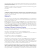
E&M Signaling Conventions 4-Wire E&M TO Mode Dedicated Transmission Only Modem for Data T1 Network Connection Up to 24 E&M or TO Interfaces in 12 Channel Increments Public or Private Network Access Bank I Stations Analog PBX 4-Wire E&M Normal Mode Figure 11-1: Normal Mode E&M Termination Carrier Network T1 PBX T1 Access Bank I Access Bank I 4-Wire E&M Tandem Mode 4-Wire E&M Tandem Mode Radio or Microwave Transceiver Radio or MicroWave tower Radio or MicroWave tower Radio or Microwave Tra
4-Wire E&M/TO Configuration interface incorporates a signaling current detector (the “ear” listening to the line). The multiplexed or carrier channel equipment always originates signaling on the E-lead coming from the transmission line. The signaling current detector is found on the M-lead going toward the transmission line. The 4-wire E&M/TO voice card can be optioned to operate either as channel equipment or switching equipment.
E&M Signaling Conventions M M-Lead Detector SB -48V E-Lead Detector -48V E SG Tandem Mode (Originating) (Switching Equipment) Normal Mode (Terminating) (Channel Equipment) E&M Type 2 Figure 11-4: E&M Signaling Type 2 M M-Lead Detector SB -48V E-Lead Detector -48V E SG Tandem Mode (Originating) (Switching Equipment) Normal Mode (Terminating) (Channel Equipment) E&M Type 4 Figure 11-5E&M Signaling Type 4 9/24/01 11-5
4-Wire E&M/TO Configuration M Tandem Mode (Originating) (Switching Equipment) -48V E E-Lead Detector -48V M-Lead Detector Normal Mode (Terminating) (Channel Equipment) E&M Type 5 Figure 11-6: E&M Signaling Type 5 11.5 Programming E&M Signaling Types 11.5.1 Jumper Switch Settings E&M signaling types I, II, IV and V (see Figure 11-3, Figure 11-4, Figure 11-5, and Figure 11-6) are configured by jumpers J1, J2 and J3 located on each channel.
Detector Configuration between the positions indicated above. This makes configuration easier by changing several connections with one move. The jumper pins are on 0.1” x 0.2” centers, making it impossible for the user to accidentally turn the jumper 90 degrees and short -48V to ground. Figure 11-7 shows the jumpers as they appear on the 4-wire E&M/TO card. Figure 11-7 also shows each of the eight possible signaling combinations as complete channel setups.
4-Wire E&M/TO Configuration Table 11-3: E&M T1 Signaling Detector XMT Signaling Bits A B Off 0 0 On 1 1 RCV Signaling Bits A B Driver 0 * On-Hook 1 * Off-Hook *Don’t care (0 or 1) 11.7 Normal and Tandem Cables Individual E&M/TO voice cards require the purchase of the Normal mode or Tandem mode cables listed below in Table 11-4. The type of cable used with the signaling line connector determines whether all twelve channels of that card operate only in that mode.
TP Busy/Idle Switch Table 11-5: 4-Position DIP Switch Settings Switch Number ON OFF 1 N/A Normal E&M 2 N/A N/A 3 N/A N/A 4 TP Idle TP Busy 11.9 TP Busy/Idle Switch Use switch 4 to select whether the tip-ground relays are closed (busy) or open (idle) during trunk processing. (Trunk processing occurs when the T1 line is in an alarm or reset state.) The Busy position (OFF) causes the tip-ground relays to be closed during a T1 alarm or reset period.
4-Wire E&M/TO Configuration T1 level = 3dBm + 16dB + 2dB - 21dB = 0dBm0 11.12 Receive (Digital-to-Analog) Gain To calculate the receive level on the T1, R1 pair, use the following formula: T1/R1 level = T1 level +åGain Switches -21dB The following is an example of setting receive gain: Suppose the T1 input level to codec is at -1dBm0. With all switches off, the output at the T1, R1 pair is -1dBm -21db = -22dBm.
E&M Normal mode cable 11.14.2 Cable Type Voice grade telephone cable 25 twisted pairs of 24 AWG seven-strand copper. Outer diameter 0.34” Two per assembly 11.14.3 Common Connector Female 96-pin DIN C-type connector (AMP 166873-5). DIN performance level II Electrical and environmental properties as per DIN 41612 and IEC 603-2 One per assembly Backshell Kit AMP 826196-1 One per assembly 11.14.
4-Wire E&M/TO Configuration C-Type 96-Pin DIN connector 005-0004 50-Conductor, solid strand 24 AWG 50-Pin AMP Champ Connectors, Male Figure 11-8: E&M Normal Mode Cable 11.15 E&M Tandem Mode Cable 11.15.1 Description E&M tandem mode cable, 96-pin DIN female to two Telco 50-pin males. 11.15.2 Cable Type: Voice grade telephone cable 25 twisted pairs of 24 AWG seven-strand copper. Outer diameter 0.34” Two per assembly 11.15.3 Common Connector: Female 96-pin DIN C-type connector (AMP 166873-5).
E&M Tandem Mode Cable Two per assembly Adjustable cable clamp (AMP 552763-2) Two per assembly Backshell Kit (AMP 552760-2) Two per assembly 11.15.5 Markings: Blue 1.5” long piece of heat shrink tubing on each cable near Telco connector Silk screen as shown below on DIN connector backshell. 11.15.6 Length 10 feet 11.15.
4-Wire E&M/TO Configuration Table 11-7(Part 1): Connector Pinouts for Cable P/N 005-0004 RJ2HX Punchdown Block E&M Type I, II, IV, V Normal Mode Note: Telco Pinouts 1 & 26, 2 & 27, 3 & 28, etc.
E&M Tandem Mode Cable Table 11-7 (Part 2): Connector Pinouts for Cable P/N 005-0004 RJ2HX Punchdown Block E&M Type I, II, IV, V Normal Mode Note: Telco Pinouts 1 & 26, 2 & 27, 3 & 28, etc.
4-Wire E&M/TO Configuration Table 11-8 (Part 1): Connector Pinouts for Cable P/N 005-0005 RJ2HX Punchdown Block E&M Type I, II, IV, V Normal Mode Note: Telco Pinouts 1 & 26, 2 & 27, 3 & 28, etc.
E&M Tandem Mode Cable Table 11-8 (Part 2): Connector Pinouts for Cable P/N 005-0005 RJ2HX Punchdown Block E&M Type I, II, IV, V Normal Mode Note: Telco Pinouts 1 & 26, 2 & 27, 3 & 28, etc.
4-Wire E&M/TO Configuration 11-18 9/24/01
About This Chapter Chapter 12 Diagnostics & Troubleshooting Contents of This Chapter: About This Chapter .................................... 1 Diagnostic Switches ................................... 1 Self Test 1 and 2 ........................................ 2 Self Test Fault Indications ......................... 3 1 kHz Digital Milliwatt Test Signal .............. 4 Network Loopback 1 and 2 ........................ 5 T1 Line or Payload Loopbacks ................... 5 ANSI T1.403 Remote T1 LLB .........
Note: These tests as well as additional test functions can be performed using the MS Windows-based Remote Monitor software. For directions on performing Self Test loopbacks and tone transmission, enabling network loopbacks, and activating automatic Alarm Cut-Off (ACO) via the software, see the separate Remote Monitor User’s Guide. 12.3 Self Test 1 and 2 ! Caution: Because Self Test is a service-disrupting procedure. Disconnect all attached telephones prior to initiating Self Test. 12.3.
Self Test Fault Indications 2. Verify that T1 Test 1 or T1 Test 2 LED turns green after approximately 16 seconds. 12.3.2 Card Self Test At the start of the self test sequence, when the Controller asserts the self test bit toward the voice card, the following events occur on a per channel basis: • The voice card reads from the Controller and sees the self test flag at logic 1 (active). • The received A/B signaling bits are not processed since the signaling state machine is skipped in software.
12.4.3 Remote Mode: Ringback Tone or 1 Digital Milliwatt When the Access Bank II - SNMP is powered up in Remote mode, the tone sent during the Self Test can consist either of the same Ringback dual tone (440 Hz +480 Hz) sent in the Local Mode or a standard 1 kHz digital milliwatt test signal. In Remote mode, Ringback tone is the default setting. 12.
Remote Mode: Remote T1 Line or Payload Loopbacks 12.7 Remote Mode: Remote T1 Line or Payload Loopbacks In Remote mode, if the T1 line is ANSI T1.403 ESF formatted and Network Loopback detect and ESF ANSI detect both has been enabled, the two types of loopback codes the Access Bank II - SNMP can be configured to detect are Remote T1 Line and Remote Payload Loopback. The default setting in Remote mode is Remote T1 Line Loopback. 12.8 ANSI T1.
Voice Channels DS-1 Network V.35 Data These are loops in the "equipment" direction. Voice Channels DS-1 Network V.35 Data These are loops in the "network" direction. Figure 12-1: Loopback Legend 12.9.1 Self-Test Voice Channels DS-1 Network V.
Illustrations of Loops and Self-Tests 12.9.2 Equipment Loopback Voice Channels DS-1 Network V.35 Data DS1 Equipment Loopback Loop occurrs at DS1 (at framer), Check for framing & errors. It metallically loops Tx to Rx. Commands: loop d1 equipment line statistics ds1 1 current loop none Figure 12-3: Equipment Loopback 12.9.3 Equipment Loopback - Payload Voice Channels DS-1 Network V.
12.9.4 DS-1 Network Loopback Voice Channels DS-1 Network V.35 Data DS-1 Network Loop Loops at DS-1 (at framer), have DS-1 Vendor check framing/errors Commands: loop d1 network line loop none Figure 12-5: DS-1 Network Loopback 12.9.5 : DS-1 Network Loopback - Payload Voice Channels DS-1 Network V.
Illustrations of Loops and Self-Tests 12.9.6 Receiving DS-1 CSU Loopback Voice Channels DS-1 Network V.35 Data CSU Loopup Code Receiving DS-1 CSU Loop Causes a network/line loopback Loopup code sent by remote unit or network, occurs at local DS-1 CSU. D4 - line loop "Unframed" ESF AT&T Line/Payload ESF BOM Line/Loop DS-1 vendor checks framing/errors 12.9.7 Sending DS-1 CSU Loopback Voice Channels CSU Loopup Code CSU Loopup Code DS-1 Network V.
12.9.8 Sending DS-1 BERT Pattern Voice Channels BERT Pattern BERT Pattern DS-1 Network V.35 Data Send DS-1 BERT Pattern Local unit sends selectable test pattern, for a full T1 @ 64 kBps/Channel. Check for sync/errors across network, use "send error" to inject one error. Commands: ds1 d1 send network QRSS ds1 d1 send error ds1 d1 send off Figure 12-8: Sending DS-1 BERT Pattern 12.9.9 V.35 Equipment Loopback Voice Channels DS-1 Network V.35 Data or BERT Tester V.35 Equipment Loopback Loop occurs at V.
Illustrations of Loops and Self-Tests 12.9.10 V.35 Network Loopback V.54 Loop Up Voice Channels DS-1 Network V.35 Data Application or BER Tester V.35 Data V.35 Network Loop Loops at local V.35 port (location), Check for sync and errors at remote data port, without BERT. Commands: v35 v1 network line loop none Figure 12-10: V.35 Network Loopback 12.9.11 Sending V.54 Loopback Voice Channels V.54 Loop Up Code V.54 Loop Up Code DS-1 Network V.35 Data V.35 Data Send V.54 Loop Local unit sends V.
12.9.12 Receiving V.54 Loopback V.54 Loop Up Code Voice Channels V.35 Data Application or BER Tester DS-1 Network V.35 Data Receiving V.54 Loop Remote unit or network sends V.54 loop up code, loop occurs at local data port. Check for errors on remote data port, without BERT. Figure 12-12: Receiving V.54 Loop 12.9.13 Sending FX Ring or Tone Ringing or 1004 Hz Tone Voice Channels DS-1 Network V.
LED Test and Status Indicators SNMP Control Panel. Setting this switch to the Alarm Cut-Off position (ON) opens the alarm relay contacts (150 Vrms, 150 mA maximum load) that close when the Access Bank II - SNMP enters an alarm state. Table 9-3 defines the pin functions on the 50-pin Tip & Ring jack.
Table 12-5: T1 Test LEDs for T1 Span 1 and 2 State GREEN FLASHING GREEN RED YELLOW FLASHING YELLOW Meaning Normal operations. Trunk processing, self test, and network loopback inactive. T1 Self Test local loopback passed. T1 Self Test local loopback failed due to one or more of the following conditions: T1 Loss of Signal, Out of Frame, Improper Line Code Received, ESF or BPV errors received. Channels held in Trunk Processing for this T1 span. Network loopback active for this T1 span. Table 12-6: V.
Fault Isolation Procedures Table 12-7: Control Panel LED Indications Symptom All LED test and status indicators are OFF. T1 Span 1 or 2 LED is RED. Corrective Action Indicates a loss of power or excessive voltage to the Access Bank II - SNMP. To correct the problem: 1 Verify that the Power Conversion Cube is plugged into an active AC outlet and the power switch on the power converter is turned on. 2 Check the circuit breaker on the Power Conversion Cube.
T1 Test 1 or 2 LED is RED. T1 Test 1 or 2 LED flashes YELLOW. If the T1 Test LEDs remain red for more than 16 seconds after a Self Test is initiated, the Access Bank II - SNMP has failed the Self Test. To correct the problem: 1 Verify that the Controller card and at least one voice card are in place. 2 Power down the Access Bank II - SNMP for 60 seconds, power it up again, and repeat the Self Test.
Access Bank II - SNMP Shuts Down for No Apparent Reason 1. Check the voice cable for a loose connection. 2. Check the voice cable for a broken/open pair. 3. Use Remote Monitor software to run a Self Test Loopback with the Ringback tone. If no ringing tone is heard at the drop, the ringback generator on the Controller card may be faulty. Replace the Controller card using the procedure given in the Maintenance section. 12.
12-18 9/24/01
About This Chapter Chapter 13 Maintenance Contents of This Chapter: About This Chapter .................................... 1 Replacing a Voice Card ............................. 2 Replacing the Controller Card ................... 3 13.
13.2 Replacing a Voice Card To replace a voice card while the Access Bank II - SNMP is hot, refer to Figure 13-1, then follow these steps: 1. Release the two thumb screws on the back plate of the Access Bank II - SNMP and remove the plate. 2. On the voice card you wish to remove, lift the card ejector latches to release the card from its internal connector. 3. Carefully slide the card out of the back of the Access Bank II - SNMP. 4.
Replacing the Controller Card Figure 13-1: Accessing the Voice Cards 13.3 Replacing the Controller Card To replace the Access Bank II - SNMP Controller card, follow these steps: 1. Power down the Access Bank II - SNMP. 2. Disconnect power and interface cables 3. Refer to Figure 13-2 to locate the back plate of the Access Bank II - SNMP that identifies the voice channels and any corresponding test switches. Loosen the two thumb screws and remove the back plate. 4.
card. 7. Insert the new Controller card and secure it with the five screws removed in Step 7. 8. Insert the voice card(s) and slide the chassis tray back into place. 9. Replace the back plate and tighten the two thumbscrews. 10. Tighten the thumbscrews on the front Control Panel, then reattach the power and interface cables. 11. Apply power to the Access Bank II - SNMP.
Replacing the Controller Card Figure 13-3: Replacing the Controller Card 9/24/01 13-5
13-6 9/24/01
About This Chapter Chapter 14 SNMP Management & Command Line Interface Contents of This Chapter: About This Chapter .................................... 1 Local/Remote Mode Selection ................... 1 SNMP Management .................................. 2 Command Line Interface (CLI) .................. 7 Context Sensitive Help .............................. 9 Configuration Commands ........................ 19 Status Commands ................................... 29 14.
14.3 SNMP Management The Access Bank II SNMP provides: • Built-in SNMPv2 Agent software providing network statistics, information retrieval and update, trap thresholds, and automatic transmission of trap data to Network Management Stations. • Application Support for Simple Network Management Protocol (SNMP) and Telnet, per RFC 1902 through 1907. Management Information Base (MIB), per RFC 1573. • Transport Support for Transport Control Protocol (TCP) and User Datagram Protocol (UDP), per RFC 1213.
SNMP Management objects with predefined MIB data structures. The Access Bank II/SNMP uses the Bellcore® standard MIB for T1 interfaces. Manager operations include simple “get” and “set” commands to retrieve and update MIB data in the Agent. Normally, the Manager polls the Agent periodically to check traffic statistics. However, the Manager can also set thresholds for traps.
14.3.
SNMP Management • T1 interface statistics, per RFC 1406 14.3.7 Traps The Access Bank II SNMP agent supports the following standard SNMPv2 defined traps. In the future, enterprise specific traps will be added. Interpretations of the trap values are: coldStart Trap A coldStart(0) trap signifies that the sending protocol entity is reinitializing itself such that the agent's configuration or the protocol entity implementation may be altered.
14.3.8 Maintenance The Access Bank II SNMP provides maintenance functions for the following SNMPv2 operations. • Loopback operations: T1 remote line and payload. Loopback operations verify and segment operating network interface circuits. • Fault isolation: BERT QRSS test patterns in conjunction with loopback operations. The user may also employ standard Internet PING function tests to check the connectivity at the IP layer.
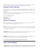
Command Line Interface (CLI) . Remote Control FXS Modem T1 Telephone Network Access Bank II SNMP Local Control Modem RS-232 VT-100 Terminal VT-100 Terminal Figure 14-3: Local and Remote RS-232 CLI Management Remote Control Telnet in data stream V.35 Frame or IP Network T1 Access Bank II SNMP Telnet Terminal Router LAN Ethernet 10Base-T Local Control Telnet Terminal Figure 14-4: Local and Remote Telnet CLI Management 14.4.
Slot Card Revision --------- --------- --------LIU AB-II SNMP 1.02 FX#1 FXS12 3.03 FX#2 FXS12 3.03 Span --------1) d1 2) d2 3) f1 4) f2 Name ---------------------------------“Long Distance Carrier” “ABI To Customer Equipment” “FXS To Customer Equipment” “Local Equipment Carrier” Access Bank > 5. If there is no Password defined, then the following screen should be displayed. Access Bank Boot Version 1.00 Management Version 1.
Command Line Interface (CLI) commands, including all levels of options for each command. Typing help after a command name provides a list of the command options at all levels. 1. Type ? at the prompt to list all of the commands, as shown below. Commands ...............Command Line Interface Help. For immediate context sensitive help, type ? at any time. For full command help, type “help” after any partial command. \ .................Enter \ to go to the top command level aco ...............
2. Type help at the prompt to list all of the commands and options, as shown below. Commands ............. CommandLineInterfaceHelp.Forimmediate context sensitive help, type ? at any time. For full command help, type “help” after any partial command. \ ................. Enter \ to go to the top command level aco ................. Display/Set Alarm Cutoff off ................ Disable alarm on ................. Enable alarm alarms ............... Display/Set current alarms all on|off .........
Command Line Interface (CLI) t11...............Set Clock Source to T1 #1 t12...............Set Clock Source to T1 #2 internal ..........Set Clock Source to internal config ...............Set/Restore Configuration code ipaddr “path” .Load app code “path” from TFTP server; Specify the ipaddr and the path including filename; System will reboot new code download ...........(Diagnostic) Download current configuration factory ............
0: FXS Loop or Ground Start 1: FXS Ground Start 2: FXS Loop Start 3: FXO Loop or Ground Start 4: FXO Ground Start 5: FXO Loop Start 6: E&M Immediate Start 7: E&M Wink Start 8: E&M Wink Start ANI/DNIS 9: E&M DPT type ............... Display DNI Channel Type s:c [n] opt ...... Set Channel Type for [n] channels from s:c clear -- for data or bypass voice -- for voice signaling dialout .............. Display/Set dialout alarm enables all on|off ......... Set all alarm enabless pager ..............
Command Line Interface (CLI) dsx0|csu0 .........DSX ( 0’-132’) or CSU 0.0 db dsx133 ............DSX (133’-265’) dsx266 ............DSX (266’-398’) dsx399 ............DSX (399’-532’) dsx533 ............DSX (440’-550’) csu7..............CSU 7.5 db csu15.............CSU 15.0 db csu22.............CSU 22.5 db linetype ...........Set DS1 Line Type esf...............ESF Line Type d4................D4 Line Type linecode ...........Set DS1 Coding Type ami...............AMI Line Coding b8zs..............
ring - ringback to fx chans (def) tone - 1KHz tone to fx chans ringback to fx ... > ds1 d1 send equipment ................. > ds1 d1 send equipment ring tone to fx ....... > ds1 d2 send equipment tone equipment ............ Display the Equipment List event ................ Display the next 18 events all ................ Display the entire Event Log clear .............. Clear the Event Log first .............. Display the first 18 events exit ................. Exit Command Line Interface ip .................
Command Line Interface (CLI) carrier on|off ..Loss of carrier detected csuloop on|off ..CSU loop code received unframed on|off ..Unframed, all 1’s received sync on|off ..Loss of sync yellow on|off ..Yellow alarm received bpv on|off ..BPVs exceed 1544 in 15 min period ses on|off ..SES exceed 10 in 15 min period unavail on|off ..Unavailable seconds in 15 min period fdlline on|off ..FDL line loop request received fdlpay on|off ..FDL payload loop request received loop .................
rs232 ................ Display/Set Optional Data RS-232 Port baud ............... Set Async Subrate Baud Rate b9600 ............ 9600 baud b19200 ........... 19200 baud b38400 ........... 38400 baud b57600 ........... 57600 baud data ............... Set Async Subrate Data Size bit7 ............ 7 bit data bit8 ............ 8 bit data parity ............ Set Parity even ............ Even Async Subrate Parity none ............. No Parity odd .............. Odd Parity speed ............. Set Synch Speed k56 ..
Command Line Interface (CLI) interface ..........IP Interface leds ...............Leds on unit signal .............FX Signal Type by Channel snmp ...............SNMP Interface tcp ................TCP Interface udp ................UDP Interface xmodem .............XMODEM Interface telnet ...............Set Telnet Session Configuration echo ...............Echo Telnet output on serial line off...............Disable echo on................Enable echo time .................Display/Set Time: time hr:mm:ss trap .
p2to15 - O.151 p2to20 - QRSS w/o bit stuffing p2to23 - O.151 qrss - QRSS pattern (default) zeros - all zeros r - optional error rate 0 - disable errors (default) r=1-7 - error rate of 10^-r QRSS to net ...... v35 v1 send network > v35 v1 send network qrss equipment ........ Send Pattern to Equipment [p] [r] ........ p - optional pattern alt - alternating 1/0 d4up - D4 loopup: 00001 d4dn - D4 loopdown: 001 ones - all ones p1in8 - 00000001 p511 - O.153 p2047 - O.152 p2to15 - O.
Command Line Interface (CLI) Operations Type To turn the Alarm Cutoff on aco on To turn the Alarm Cutoff off aco off To display the status of the Alarm Cutoff aco Comments 14.4.4.2 alarms Use the alarms command to turn on and off, the Access Bank alarms.
There are no options for this command. To initiate a reboot, type boot and press return. 14.4.4.5 clk Use the clk command to set the system clock sources. The Access Bank II - SNMP allows the user to configure a primary and secondary clock source. Operations Type Comments To set primary clock source to T1 #1 clk primary T1 1 This sets the primary system to clock to be derived from T1 #1.
Command Line Interface (CLI) Operations Type Comments To display all connections connections Displays all connections and group definitions. To display bypass connections connections bypass Displays only bypass connections between spans. A Bypass connection is a nailed up configuration and doesn’t utilize the switch state logic. 14.4.4.8 craft Use the craft command to set and display all options of the craft port.
14.4.4.10dni Use the dni command to set the DNI properties for voice channels. Operations Type To set signal type for n dni s:c [n] opt Comments channels from s:c To display signal type dni signal To set DNI channel type dni type s:c [n] opt To display DNI channel type dni type 14.4.4.11dialout Use the dialout command to set and display enabling for the dialout alarms.
Command Line Interface (CLI) 14.4.4.13 event Use the event command to display or clear the event log. Operations Type To display the next 18 events event To display the entire event log event all To display the first 18 events event first To clear the event log event clear Comments 14.4.4.14 exit Use the exit command to end the current management session. Operations Type Comments To end current session exit Ends current session 14.4.4.
14.4.4.16 kill Use the kill command to remove time slot connections. This command is used to kill static connections and group definitions. Operations Type Comments To remove a bypass connection on T1 #1 kill bypass d1:24 Kills the connection for slot 24 on T1 #1 To display command Help kill ? 14.4.4.17 loop Use the loop command to display, disable and enable loopbacks.
Command Line Interface (CLI) Operations Type Comments To make bypass for group v1 in ds1 #2 channels 1 and 2 make bypass v1 d2:1 2 Configures a v.35 data connection on channels 1 and 2 of T1 #2 To make group assignment for group b in fxs #2 channels 1 to 12 make group b f2:1 12 Configures voice card channels 1..12 to group B. To display Help make ? 14.4.4.20 name Use the name command to set or display names of circuit IDs, session prompt, and system name.
Operations Type Comments To validate that a node on the network can be reach via the Access Bank II - SNMP ping 192.127.20.10 Sends one Ping to the indicated ipaddr To send IP ping 4 times with 50 ml delay between pings ping 192.127.20.10 4 50 Sends 4 Pings to the indicated ipaddr with 50 ms delay between pings To display Help ping? 14.4.4.23 rs232 Use the rs232 command to configure the RS232 port. To see all the options for this command, type rs232 help. 14.4.4.
Command Line Interface (CLI) event and alarm logs. Operations Type To configure the clock for the time time 08:04:00 To display date & time date Comments 14.4.4.28 trap Use the trap command to send a warm start trap to SNMP, or to send a link up or down trap to an interface. Operations Type To send a warm start trap to SNMP trap To send a link up trap to an interface trap n up To send a link down trap to an interface trap n down Comments n is the interface number (1 or 2) 14.4.4.
14.4.4.30 v35 Use the v35 command to configure parameters for the V.35 data port to be accessed by the SNMP manager via RFC-1659. Operations Type Comments To set the circuit ID to “V.35 - 1” v35 circuitid “V.35 - 1” Sets the Circuit Id for the V.35 port To set clock inversion to receive clock inverted v35 clkinv rx Sets the receive clock to be inverted. To set CTS to follow RTS signal v35 cts rts Sets CTS to follow RTS signal To set data inversion v35datainv invert Sets the V.
Command Line Interface (CLI) 14.4.5.2 log Use the log command to display the current alarm history log. Operations Type Comments To display the alarm history log log Index Time 1 0 Date Alarm 00:03:06 01/01/96 Log in 00:00:00 01/01/96 Power on 14.4.5.3 statistics Use the statistics command to display ds1, channel and group performance.
14-30 Operations Type Comments To display the status of the interfaces status all Displays the status of all the interfaces To display the status of the Ethernet Interface status ethernet Displays status and performance numbers for the ethernet Interface To display the status of the IP interface status interface Displays the current performance and status for the IP layer of the Management protocol stack.
GLOSSARY 10Base-T: 10Base-T is an IEEE standard for operating Ethernet local area networks (LANs) on twistedpair cabling using the home run method of wiring (the same as the phone company uses) and a wiring hub that contains electronics performing similar functions to a central telephone switch. The full name for the standard is IEEE 802.3 10Base-T.
CHANNEL SERVICE UNIT: See DSU/CSU CONNECTION: A connection is a logical linkage between timeslots on a span or between spans. CROSSTALK: Crosstalk occurs when you can hear someone you did not call talking on your telephone line to another person you did not call. You may also only hear half the other conversation (i.e. just one person speaking). There are several technical causes for crosstalk relating to cable placement, shielding and transmission techniques.
DNIS (DIRECTORY NUMBER IDENTIFICATION SERVICE): DNIS is a feature of 800 and 900 lines that provides the number of the caller dialed to reach the attached computer telephony system. Using DNIS capabilities, one trunk group can be used to serve multiple applications. The DNIS number can be provided in a number of ways, inband or out-of-band, ISDN or via a separate dedicated data channel.
Access Bankô II, that incorporates a controller, channel service unit (CSU), ringing generator and power converter on a single card to interface between the T1 network and the analog functions of the channel bank. PBX (PRIVATE BRANCH EXCHANGE): PERFORMANCE REPORT MESSAGE (PRM): PLAR (PRIVATE LINE AUTOMATIC RINGDOWN): A leased voice circuit that connects two single telephone handsets together. Whenever either handset is lifted, the other instrument automatically rings.
naling. TRUNK PROCESSING (TP): WINK: A signal sent between two telecommunications devices as part of a handshaking protocol. It is a momentary interruption in SF (Single Frequency) tone, indicating that the distant Central Office (CO) is ready to receive the digits that have just been dialed. In telephone switching systems, a single supervisory pulse. On a digital connection such as a T1 circuit attached to an Access Bank II, a wink is signaled by a brief change in the A and B signaling bits.