9XL Hermetic Centrifugal Liquid Chillers 50/60 Hz With HCFC-22 and HFC-134a Start-Up, Operation, and Maintenance Instructions SAFETY CONSIDERATIONS Centrifugal liquid chillers are designed to provide safe and reliable service when operated within design specifications. When operating this equipment, use good judgment and safety precautions to avoid damage to equipment and property or injury to personnel.
CONTENTS Page SAFETY CONSIDERATIONS . . . . . . . . . . . . . . . . . . . 1 INTRODUCTION . . . . . . . . . . . . . . . . . . . . . . . . . . . . . . 4 ABBREVIATIONS AND EXPLANATIONS . . . . . . . 4 CHILLER FAMILIARIZATION . . . . . . . . . . . . . . . . . . 5 Chiller Information Plate . . . . . . . . . . . . . . . . . . . . . . 5 System Components . . . . . . . . . . . . . . . . . . . . . . . . . 5 Cooler . . . . . . . . . . . . . . . . . . . . . . . . . . . . . . . . . . . . . . . 5 Condenser . . . . . . .
CONTENTS (cont) Page Check Optional Pumpout Compressor Water Piping . . . . . . . . . . . . . . . . . . . . . . . . . . . . . . . 47 Check Relief Devices . . . . . . . . . . . . . . . . . . . . . . . . 47 Inspect Wiring . . . . . . . . . . . . . . . . . . . . . . . . . . . . . . 47 Carrier Comfort Network Interface . . . . . . . . . . . 48 Check Starter . . . . . . . . . . . . . . . . . . . . . . . . . . . . . . . 48 • MECHANICAL-TYPE STARTERS • BENSHAW, INC. SOLID-STATE STARTER Oil Charge . . . . . . . . .
CONTENTS (cont) Page Water Leaks . . . . . . . . . . . . . . . . . . . . . . . . . . . . . . . . 64 Water Treatment . . . . . . . . . . . . . . . . . . . . . . . . . . . . 65 Inspect the Starting Equipment . . . . . . . . . . . . . . 65 Check Pressure Transducers . . . . . . . . . . . . . . . . 65 Optional Pumpout System Maintenance . . . . . . 65 • OPTIONAL PUMPOUT COMPRESSOR OIL CHARGE • OPTIONAL PUMPOUT SAFETY CONTROL SETTINGS Ordering Replacement Chiller Parts . . . . . . . . . .
valves, a magnetically coupled dial-type refrigerant level gage, a one-inch FPT drain valve, and a 1⁄2-in. male flare vapor connection for the pumpout unit. A 30-in.-0-400 psi (–101-0-2750 kPa) gage also is supplied with each unit. NOTE: If a storage vessel is not used at the jobsite, factoryinstalled isolation valves on the chiller may be used to isolate the chiller charge in either the cooler or condenser. An optional pumpout compressor system is used to transfer refrigerant from vessel to vessel.
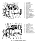
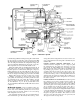
1 2 3 4 5 6 7 8 9 10 11 12 13 14 — — — — — — — — — — — — — — 15 16 17 18 19 20 21 22 23 24 25 26 — — — — — — — — — — — — 27 — 28 — 19XL FRONT VIEW 29 30 31 32 33 34 35 — — — — — — — 36 37 38 39 40 41 42 43 44 45 46 — — — — — — — — — — — LEGEND Unit-Mounted Starter Refrigerant Filter Drier Rigging Guide Bolt Refrigerant Moisture Indicator Motor Sight Glass Refrigerant Motor Drain Oil Filter Access Cover Refrigerant Oil Cooler Oil Level Sight Glasses Guide Vane Actuator Typical Flange Connection Con
5 4 6 8 7 9 10 1 2 3 4 5 6 7 8 9 10 11 12 11 24 23 12 22 13 — — — — — — — — — — — — 13 — 14 — 15 — 21 20 19 18 17 16 16 17 18 19 20 21 22 23 15 14 19XL FRONT VIEW — — — — — — — — 24 — 25 26 27 28 29 30 31 42 32 41 40 39 38 37 LEGEND Unit-Mounted Starter Refrigerant Filter Drier Rigging Guide Bolt Motor Sight Glass Refrigerant Moisture Indicator Refrigerant Oil Cooler Oil Filter Access Cover Oil Level Sight Glasses Guide Vane Actuator Typical Flange Connection Control Cent
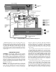
Fig. 3 — Refrigerant Motor Cooling and Oil Cooling Cycles when the compressor is shut down. The oil level should be visible in at least one of the 2 sight glasses during operation. Oil sump temperature is displayed on the LID default screen. Oil sump temperature ranges during compressor operation between 100 to 120 F (37 to 49 C) [120 to 140 F (49 to 60 C)]. Refrigerant that flows to the oil cooling system is regulated by a thermostatic expansion valve.
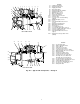
Fig. 4 — Lubrication System casing will vent this refrigerant into the suction of the compressor. Oil entrained in the refrigerant is eliminated by the demister filter. journal bearings within the bearing housing. The oil then drains into the oil reservoir at the base of the compressor. The PIC (Product Integrated Control) measures the temperature of the oil in the sump and maintains the temperature during shutdown (see Oil Sump Temperature Control section, page 32).
STARTING EQUIPMENT The 19XL requires a motor starter to operate the centrifugal hermetic compressor motor, the oil pump, and various auxiliary equipment. The starter serves as the main field wiring interface for the contractor. Three types of starters are available from Carrier Corporation: solid-state, wye-delta, and across-the-line starters. See Carrier Specification Z-375 for specific starter requirements.
• • • • overtemperature ground fault current unbalance run state These LEDs are further explained in the Check Starter and Troubleshooting Guide section, page 66. The memory of the PSIO and LID modules are volatile. If the battery in a module is removed or damaged, all programming will be lost. General — The 19XL hermetic centrifugal liquid chiller contains a microprocessor-based control center that monitors and controls all operations of the chiller.
Fig. 8 — 19XL Controls and Sensor Locations Fig. 9 — Control Sensors (Temperature) 1 2 3 4 5 6 Fig. 10 — Control Sensors (Pressure Transducer, Typical) — — — — — — LEGEND LID PSIO 8-Input Module (One of 2 Available) 5-Volt Transducer Power Supply 6-Pack Relay Board Circuit Breakers (4) Fig.
PROCESSOR MODULE (PSIO) — The PSIO is the brain of the PIC (Fig. 11). This module contains all the operating software needed to control the chiller. The 19XL uses 3 pressure transducers and 8 thermistors to sense pressures and temperatures. These are connected to the PSIO module. The PSIO also provides outputs to the guide vane actuator, oil pump, oil heater, hot gas bypass (optional), motor cooling solenoid, and alarm contact.
ALARMS AND ALERTS — Alarm (*) and alert (!) status are indicated on the Status tables. An alarm (*) will shut down the compressor. An alert (!) notifies the operator that an unusual condition has occurred. The chiller will continue to operate when an alert is shown. Alarms are indicated when the control center alarm light (!) flashes. The primary alarm message is viewed on the default screen and an additional, secondary, message and troubleshooting information are sent to the Alarm History table.
• Press EXIT to return to the previous screen level. 4. On the Point Status table press NEXT or PREVIOUS until desired point is displayed on the screen. • Press INCREASE or DECREASE to change the highlighted point value. OVERRIDE OPERATIONS To Override a Value or Status 1. On the Point Status table press NEXT PREVIOUS to highlight the desired point. or TO VIEW POINT STATUS (Fig.
3. Press RELEASE to remove the override and return the point to the PIC’s automatic control. 4. Press NEXT or PREVIOUS to highlight the desired period or override that you wish to change. Override Indication— An override value is indicated by ‘‘SUPVSR,’’ ‘‘SERVC,’’ or ‘‘BEST’’ flashing next to the point value on the Status table. 5. Press SELECT to access the highlighted period or override. TIME SCHEDULE OPERATION (Fig. 16) 1. On the Menu screen, press SCHEDULE . 6. a.
*Only available on PSIO Software Version 09 and higher. †Available on PSIO Software Versions 07 and 08. Fig.
Fig.
*Only available on PSIO Software Version 09 and higher. †Available on PSIO Software Versions 07 and 08. Fig.
TO VIEW AND CHANGE SET POINTS (Fig. 19) 3. Press NEXT or PREVIOUS to highlight the desired set point entry. 1. To view the Set Point table, at the Menu screen press SETPOINT . 4. Press SELECT to modify the highlighted set point. 2. There are 4 set points on this screen: Base Demand Limit; LCW Set Point (leaving chilled water set point); ECW Set Point (entering chilled water set point); and ICE BUILD set point (PSIO Software Version 09 and higher only).
Table 2 — LID Screens NOTES: 1. Only 12 lines of information appear on the LID screen at any given time. Press NEXT or PREVIOUS to highlight a point or to view points below or above the current screen. 2. The LID may be configured in English or SI units, as required, through the LID configuration screen. 3. Data appearing in the Reference Point Names column is used for CCN operations only. 4.
Table 2 — LID Screens (cont) EXAMPLE 2 — STATUS02 DISPLAY SCREEN To access this display from the LID default screen: 1. Press MENU . 2. Press STATUS . 3. Scroll down to highlight STATUS02. 4. Press SELECT .
Table 2 — LID Screens (cont) EXAMPLE 5 — CONFIGURATION (CONFIG) DISPLAY SCREEN To access this display from the LID default screen: 1. Press MENU . 2. Press SERVICE . 3. Scroll down to highlight EQUIPMENT CONFIGURATION. 4. Press SELECT . 5. Scroll down to highlight CONFIG. 6. Press SELECT .
Table 2 — LID Screens (cont) EXAMPLE 7 — SERVICE1 DISPLAY SCREEN To access this display from the LID default screen: 1. Press MENU . 2. Press SERVICE . 3. Scroll down to highlight EQUIPMENT SERVICE. 4. Press SELECT . 5. Scroll down to highlight SERVICE1. 6. Press SELECT .
Table 2 — LID Screens (cont) EXAMPLE 8 — SERVICE2 DISPLAY SCREEN To access this display from the LID default screen: 1. Press MENU . 2. Press SERVICE . 3. Scroll down to highlight EQUIPMENT SERVICE. 4. Press SELECT . 5. Scroll down to highlight SERVICE2. 6. Press SELECT .
Table 2 — LID Screens (cont) EXAMPLE 10 — MAINTENANCE (MAINT01) DISPLAY SCREEN To access this display from the LID default screen: 1. Press MENU . 2. Press SERVICE . 3. Scroll down to highlight ALGORITHM STATUS. 4. Press SELECT . 5. Scroll down to highlight MAINT01.
Table 2 — LID Screens (cont) EXAMPLE 12 — MAINTENANCE (MAINT03) DISPLAY SCREEN To access this display from the LID default screen: 1. Press MENU . 2. Press SERVICE . 3. Scroll down to highlight CONTROL ALGORITHM STATUS. 4. Press SELECT . 5. Scroll down to highlight MAINT03. 6. Press SELECT .
DEMAND LIMITING — The PIC will respond to the ACTIVE DEMAND LIMIT set point by limiting the opening of the guide vanes. It will compare the set point to either COMPRESSOR MOTOR LOAD or COMPRESSOR MOTOR CURRENT (percentage), depending on how the control is configured for the DEMAND LIMIT SOURCE which is accessed on the SERVICE1 table. The default setting is current limiting.
To give a better warning as to the operating condition of the chiller, the operator also can define alert limits on various monitored inputs. Safety contact and alert limits are defined in Table 3. Alarm and alert messages are listed in the Troubleshooting Guide section, page 66.
Table 3 — Protective Safety Limits and Control Settings MONITORED PARAMETER TEMPERATURE SENSORS OUT OF RANGE LIMIT APPLICABLE COMMENTS –40 to 245 F (–40 to 118.3 C) Must be outside range for 2 seconds PRESSURE TRANSDUCERS OUT OF RANGE 0.08 to 0.98 Voltage Ratio Must be outside range for 2 seconds. Ratio = Input Voltage ÷ Voltage Reference COMPRESSOR DISCHARGE TEMPERATURE MOTOR WINDING TEMPERATURE BEARING TEMPERATURE .220 F (104.4 C) Preset, alert setting configurable .220 F (104.4 C) .
on the LID Equipment Configuration table, Config table (see Table 2). Motor load is the default type. Ramp Loading Control — The ramp loading control slows down the rate at which the compressor loads up. This control can prevent the compressor from loading up during the short period of time when the chiller is started, and the chilled water loop has to be brought down to normal design conditions. This helps reduce electrical demand charges by slowly bringing the chilled water to control point.
3 times every 12 hours. If more than 8 starts in 12 hours occur, then an Excessive Starts alarm is displayed, preventing the chiller from starting. The operator must reset the alarm at the LID in order to override the starts counter and start the chiller. If Automatic Restart After a Power Failure is not activated when a power failure occurs, and the remote contact is closed, the chiller will indicate an alarm because of the loss of voltage.
RESET TYPE 1—Reset Type 1 requires an optional 8-input module. It is an automatic chilled water temperature reset based on a 4 to 20 mA input signal. This type permits up to ± 30° F (± 16° C) of automatic reset to the chilled water or brine temperature set point, based on the input from a 4 to 20 mA signal. This signal is hardwired into the number one 8-input module. If the 4-20 mA signal is externally powered from the 8-input module, the signal is wired to terminals J1-5(+) and J1-6(–).
The algorithm first determines if corrective action is necessary. This is done by checking 2 sets of operator configured data points, which are the MINIMUM and the MAXIMUM Load Points, (T1/P1;T2/P2). These points have default settings for each type of refrigerant, HCFC-22 or HFC-134a, as defined on the Service1 table, or on Table 4. These settings and the algorithm function are graphically displayed in Fig. 20 and 21.
If the address assignments placed into the LAG ADDRESS and STANDBY ADDRESS values conflict, the lead/ lag will be disabled and an alert (!) message will occur. For example, if the LAG ADDRESS matches the lead chiller’s address, the lead/lag will be disabled and an alert (!) message will occur. The lead/lag maintenance screen (MAINT04) will display the message ‘INVALID CONFIG’ in the LEAD/LAG CONFIGURATION and CURRENT MODE fields.
is disabled, the ACTIVE DEMAND LIMIT and the CONTROL POINT are forced to the same value as the lead chiller. AUTO. RESTART AFTER POWER FAILURE — When an auto. restart condition occurs, each chiller may have a delay added to the start-up sequence, depending on its lead/ lag configuration. The lead chiller does not have a delay. The lag chiller has a 45-second delay. The standby chiller has a 90-second delay. The delay time is added after the chiller water flow verification.
NOTE: Overriding the CHILLER START/STOP, WATER/ BRINE CONTROL POINT, and ACTIVE DEMAND LIMIT variables by CCN devices (with a priority less than 4) during the ice build period is not possible. However, overriding can be accomplished with CCN during two chiller lead/ lag. RETURN TO NON-ICE BUILD OPERATIONS — Upon termination of ice build, the chiller shall return to normal temperature control and start/stop schedule operation.
ATTACHING TO OTHER CCN MODULES — If the chiller PSIO has been connected to a CCN Network or other PIC controlled chillers through CCN wiring, the LID can be used to view or change parameters on the other controllers. Other PIC chillers can be viewed and set points changed (if the other unit is in CCN control), if desired from this particular LID module. To view the other devices, move to the ATTACH TO NETWORK DEVICE table. Move the highlight bar to any device number.
START-UP/SHUTDOWN/RECYCLE SEQUENCE (Fig. 24) 6. Press NEXT to highlight the holiday table that you wish to view or change. Each table is one holiday period, starting on a specific date, and lasting up to 99 days. Local Start-Up — Local start-up (or a manual start-up) is initiated by pressing the LOCAL menu softkey which is on the default LID screen.
If the STOP button is pressed, the guide vanes close to a preset amperage percent or until the guide vane is less than 2% open. The compressor will then shut off. If the chiller enters an alarm state or if the compressor enters a RECYCLE mode, the compressor will be deenergized immediately. To activate SOFT STOP AMPS THRESHOLD, view the bottom of Service1 table. Set the SOFT STOP AMPS THRESHOLD value to the percentage amps at which the motor will shut down. The default setting is 100% amps (no Soft Stop).
Safety Shutdown — A safety shutdown is identical to Using the Optional Storage Tank and Pumpout System — Refer to Pumpout and Refrigerant Transfer a manual shutdown with the exception that the LID will display the reason for the shutdown, the alarm light will blink continuously, and the spare alarm contacts will be energized. A safety shutdown requires that the RESET softkey be pressed in order to clear the alarm. If the alarm is still present, the alarm light will continue to blink.
Fig.
6. If no leak is found after a retest: a. Transfer the refrigerant to the storage tank and perform a standing vacuum test as outlined in the Standing Vacuum Test section, this page. b. If the chiller fails this test, check for large leaks (Step 2b). c. Dehydrate the chiller if it passes the standing vacuum test. Follow the procedure in the Chiller Dehydration section.
Table 5A — HCFC-22 Pressure — Temperature (F) TEMPERATURE (F) −50 −48 −46 −44 −42 −40 −38 −36 −34 −32 −30 −28 −26 −24 −22 −20 −18 −16 −14 −12 −10 −8 −6 −4 −2 0 2 4 6 8 10 12 14 16 18 20 22 24 26 28 PRESSURE (psi) Absolute Gage 11.67 6.154* 12.34 4.829* 13.00 3.445* 13.71 2.002* 14.45 0.498* 15.22 0.526 16.02 1.328 16.86 2.163 17.73 3.032 18.63 3.937 19.57 4.877 20.55 5.853 21.56 6.868 22.62 7.921 23.71 9.015 24.85 10.15 26.02 11.32 27.24 12.54 28.50 13.81 29.81 15.11 31.16 16.47 32.56 17.87 34.01 19.32 35.
Table 5C — HFC-134a Pressure — Temperature (F) TEMPERATURE (F) 0 2 4 6 8 10 12 14 16 18 20 22 24 26 28 30 32 34 36 38 40 42 44 46 48 50 52 54 56 58 PRESSURE (psig) 6.50 7.52 8.60 9.66 10.79 11.96 13.17 14.42 15.72 17.06 18.45 19.88 21.37 22.90 24.48 26.11 27.80 29.53 31.32 33.17 35.08 37.04 39.06 41.14 43.28 45.48 47.74 50.07 52.47 54.93 TEMPERATURE (F) 60 62 64 66 68 70 72 74 76 78 80 82 84 86 88 90 92 94 96 98 100 102 104 106 108 110 112 114 116 118 PRESSURE (psig) 57.46 60.06 62.73 65.47 68.29 71.
Fig. 27 — Typical Optional Pumpout System Piping Schematic with Storage Tank Fig.
Chiller Dehydration — Dehydration is recommended if the chiller has been open for a considerable period of time, if the chiller is known to contain moisture, or if there has been a complete loss of chiller holding charge or refrigerant pressure. Inspect Water Piping — Refer to piping diagrams provided in the certified drawings, and the piping instructions in the 19XL Installation Instructions manual. Inspect the piping to the cooler and condenser.
To attach the CCN communication bus wiring, refer to the certified drawings and wiring diagrams. The wire is inserted into the CCN communications plug (COMM1) on the PSIO module. This plug also is referred to as J5. NOTE: Conductors and drain wire must be 20 AWG (American Wire Gage) minimum stranded, tinned copper. Individual conductors must be insulated with PVC, PVC/ nylon, vinyl, Teflon, or polyethylene.
3. Some dashpot-type magnetic overload relays must be filled with oil on the jobsite. If the starter is equipped with devices of this type, remove the fluid cups from these magnetic overload relays. Add dashpot oil to cups per instructions supplied with the starter. The oil is usually shipped in a small container attached to the starter frame near the relays. Use only dashpot oil supplied with the starter. Do not substitute.
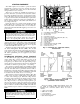
Oil Charge — The 19XL compressor holds approximately 8 gal. (30 L) of oil. The chiller will be shipped with oil in the compressor. When the sump is full, the oil level should be no higher than the middle of the upper sight glass and minimum level is the bottom of the lower sight glass (Fig. 2A or 2B). If oil is added, it must meet Carrier’s specification for centrifugal compressor usage as described in the Oil Specification section on page 63.
MODIFY CONTROLLER IDENTIFICATION IF NECESSARY — The controller identification screen is used to change the PSIO module address. Change this address for each chiller if there is more than one chiller at the jobsite. Write the new address on the PSIO module for future reference. Change the LID address if there is more than one chiller on the jobsite. Access the LID configuration screen to view or modify this address.
Table 6 — Amps Correction Factors for 19XL Motors VOLT/ Hz 200/60 208/60 220/60 230/60 240/60 360/60 380/60 400/60 440/60 460/60 480/60 550/60 575/60 600/60 3300/60 2400/60 4160/60 220/50 230/50 240/50 320/50 346/50 360/50 380/50 400/50 415/50 3000/50 3300/50 CB 4 5 3 5 5 4 7 7 3 5 7 4 4 8 4 4 4 3 4 5 2 4 5 5 6 8 3 4 CC 5 5 4 6 6 2 4 5 3 4 5 2 4 5 4 4 4 1 2 3 2 4 5 2 4 5 2 3 CD 3 5 2 4 4 4 6 8 2 3 4 3 4 6 4 3 3 2 2 5 2 3 4 3 4 5 2 3 MOTOR CODE CE CL CM CN 6 3 2 3 8 4 2 4 2 2 3 1 4 3 5 2 4 3 8 2 2 2 2 1
Table 7 — Control Test Menu Functions Loosen the compressor holddown bolts to allow free spring travel. Open the compressor suction and discharge service valves. Check that oil is visible in the compressor sight glass. Add oil if necessary. TESTS TO BE PERFORMED 1. Automated Tests* DEVICES TESTED Operates the second through seventh tests 2.
vessels. Charge the refrigerant as a gas until the system pressure exceeds 68 psig (469 kPa); [35 psig (141 kPa)]. After the chiller is beyond this pressure the refrigerant should be charged as a liquid until all of the recommended refrigerant charge has been added. 19XL CHILLER EQUALIZATION WITH PUMPOUT UNIT — The following procedure describes how to equalize refrigerant pressure on an isolated 19XL chiller using the pumpout unit. 1. Access the TERMINATE LOCKOUT mode in the Control Test. 2.
INITIAL START-UP Preparation — Before starting the chiller, check that the: 1. Power is on to the main starter, oil pump relay, tower fan starter, oil heater relay, and the chiller control center. 2. Cooling tower water is at proper level, and at or below design entering temperature. 3. Chiller is charged with refrigerant and all refrigerant and oil valves are in their proper operating position. 4. Oil is at the proper level in the reservoir sight glasses. 5.
MOTOR COMPRESSOR ASSEMBLY — Guide vane actuator, transmission, motor cooling system, oil cooling system, temperature and pressure sensors, oil sight glasses, integral oil pump, isolatable oil filter, extra oil and motor temperature sensors, synthetic oil, and compressor serviceability. MOTOR COMPRESSOR LUBRICATION SYSTEM — Oil pump, cooler filter, oil heater, oil charge and specification, operating and shutdown oil level, temperature and pressure, and oil charging connections.
of 5 to 10 lbs (2.27 to 4.5 kg) of refrigerant to prevent air from leaking into the chiller. If freezing temperatures are likely to occur in the chiller area, drain the chilled water, condenser water, and the pumpout condenser water circuits to avoid freeze-up. Keep the waterbox drains open. Leave the oil charge in the chiller with the oil heater and controls energized to maintain the minimum oil reservoir temperature. 2.
Press. Temp In Out GPM In Out Temp Press. In Out GPM CONDENSER Water Pressure Temp Refrigerant In Out Temp CHILLER SERIAL NO. BEARING TEMP Press. Diff. Temp (reservoir) Level COMPRESSOR Oil Motor FLA Amperage (or vane position) REFRIGERANT TYPE Fig. 33 — Refrigeration Log REMARKS: Indicate shutdowns on safety controls, repairs made, oil or refrigerant added or removed, air exhausted and water drained from dehydrator. Include amounts.
PUMPOUT AND REFRIGERANT TRANSFER PROCEDURES Preparation — The 19XL may come equipped with an optional storage tank or pumpout system, or a pumpout compressor. The refrigerant can be pumped for service work to either the cooler/compressor vessel or the condenser vessel by using the optional pumpout system. If a storage tank is supplied, the refrigerant can be isolated in the external storage tank.
then shut off the pumpout compressor. Warm condenser water will boil off any entrapped liquid refrigerant and chiller pressure will rise. e. When the pressure rises to 70 psig (483 kPa) [40 psig (276 kPa)], turn on the pumpout compressor until the pressure again reaches 65 psig (448 kPa) [30 psig (207 kPa)], and then turn off the compressor. Repeat this process until the pressure no longer rises, then turn on the pumpout compressor and pump out until the pressure reaches 18 in. Hg (40 kPa absolute). f.
TRANSFER ALL REFRIGERANT TO CHILLER COOLER/COMPRESSOR VESSEL 1. Push refrigerant into the chiller cooler vessel. a. Valve positions: VALVE CONDITION 1a 1b 2 C 3 4 5 C 8 C 11 12 C GENERAL MAINTENANCE Refrigerant Properties — HCFC-22 or HFC-134a 13 C is the standard refrigerant in the 19XL. At normal atmospheric pressure, HCFC-22 will boil at –41 F (–40 C) and HFC-134a will boil at –14 F (–25 C) and must, therefore, be kept in pressurized containers or storage tanks.
HCFC-22 and HFC-134a should not be mixed with air or oxygen and pressurized for leak testing. In general, neither refrigerant should not be allowed to be present with high concentrations of air or oxygen above atmospheric pressures, as the mixture can undergo combustion. REFRIGERANT TRACER — Use an environmentally acceptable refrigerant as a tracer for leak test procedures.
10. Remove the hose from the charging valve, open the isolation valves to the filter housing, and turn on the power to the pump and the motor. SCHEDULED MAINTENANCE Establish a regular maintenance schedule based on the actual chiller requirements such as chiller load, run hours, and water quality. The time intervals listed in this section are offered as guides to service only. Oil Specification — The 19XL compressor holds approximately 11.7 gal. (44.3 L) of oil.
Inspect Refrigerant Float System — Perform Compressor Bearing and Gear Maintenance — The key to good bearing and gear maintenance is inspection every 5 years or when the condenser is opened for service. Transfer the refrigerant into the cooler vessel or into a storage tank. Remove the float access cover. Clean the chamber and valve assembly thoroughly. Be sure that the valve moves freely. Make sure that all openings are free of obstructions. Examine the cover gasket and replace if necessary. See Fig.
Oil should be visible in one of the compressor sight glasses both during operation and at shutdown. Always check the oil level before operating the compressor. Before adding or changing oil, relieve the refrigerant pressure as follows: 1. Attach a pressure gage to the gage port of either compressor service valve (Fig. 35). 2. Close the suction service valve and open the discharge line to the storage tank or the chiller. 3. Operate the compressor until the crankcase pressure drops to 2 psig (13 kPa). 4.
at the sensor plugs. Check the sensor wire at the sensor for 5 vdc if the control is powered. TROUBLESHOOTING GUIDE Overview — The PIC has many features to aid the operator and the technician in troubleshooting a 19XL chiller. • By using the LID display, the chiller actual operating conditions can be viewed while the unit is running. • When an alarm occurs, the default LID screen will freeze at the time of alarm. The freeze enables the operator to view the chiller conditions at the time of alarm.
If the transducer value is not within the calibration range, the transducer will return to the original reading. If the LID pressure value is within the allowed range (noted above), check the voltage ratio of the transducer. To obtain the voltage ratio, divide the voltage (dc) input from the transducer by the supply voltage signal, measured at the PSIO terminals J7-J34 and J7-J35. For example, the condenser transducer voltage input is measured at PSIO terminals J7-1 and J7-2.
Table 9 — LID Primary and Secondary Messages and Custom Alarm/Alert Messages with Troubleshooting Guides A. SHUTDOWN WITH ON/OFF/RESET-OFF PRIMARY MESSAGE SECONDARY MESSAGE MANUALLY STOPPED — PRESS CCN OR LOCAL TO START TERMINATE PUMPDOWN MODE TO SELECT CCN OR LOCAL SHUTDOWN IN PROGRESS COMPRESSOR UNLOADING SHUTDOWN IN PROGRESS COMPRESSOR DEENERGIZED ICE BUILD OPERATION COMPLETE PROBABLE CAUSE/REMEDY PIC in OFF mode, press the CCN or local softkey to start unit.
Table 9 — LID Primary and Secondary Messages and Custom Alarm/Alert Messages with Troubleshooting Guides (cont) C. IN RECYCLE SHUTDOWN PRIMARY MESSAGE SECONDARY MESSAGE RECYCLE RESTART PENDING OCCUPIED MODE RECYCLE RESTART PENDING REMOTE CONTACT CLOSED RECYCLE RESTART PENDING START COMMAND IN EFFECT RECYCLE RESTART PENDING ICE BUILD MODE PROBABLE CAUSE/REMEDY Unit in recycle mode, chilled water temperature is not high enough to start.
Table 9 — LID Primary and Secondary Messages and Custom Alarm/Alert Messages with Troubleshooting Guides (cont) F. START-UP FAILURES: This is an alarm condition. A manual reset is required to clear. PRIMARY MESSAGE FAILURE TO START LOW OIL PRESSURE OILPD [VALUE] exceeded limit of [LIMIT]*. Check oil pump system. FAILURE TO START OIL PRESS SENSOR FAULT OILPD [VALUE] exceeded limit of [LIMIT]*. Check oil pressure sensor.
Table 9 — LID Primary and Secondary Messages and Custom Alarm/Alert Messages with Troubleshooting Guides (cont) G. COMPRESSOR JUMPSTART AND REFRIGERANT PROTECTION PRIMARY MESSAGE SECONDARY MESSAGE ALARM MESSAGE/PRIMARY CAUSE UNAUTHORIZED OPERATION UNIT SHOULD BE STOPPED CA P Emergency: Compressor running without control authorization. POTENTIAL FREEZE-UP EVAP PRESS/TEMP TOO LOW ERT Emergency: Freeze-up prevention. FAILURE TO STOP DISCONNECT POWER RUN AUX Emergency: DISCONNECT POWER.
Table 9 — LID Primary and Secondary Messages and Custom Alarm/Alert Messages with Troubleshooting Guides (cont) I. NORMAL RUN OVERRIDES ACTIVE (ALERTS) PRIMARY MESSAGE RUN CAPACITY LIMITED RUN CAPACITY LIMITED RUN CAPACITY LIMITED RUN CAPACITY LIMITED RUN CAPACITY LIMITED SECONDARY MESSAGE HIGH CONDENSER PRESSURE HIGH MOTOR TEMPERATURE LOW EVAP REFRIG TEMP HIGH COMPRESSOR LIFT MANUAL GUIDE VANE TARGET ALARM MESSAGE/PRIMARY CAUSE CRP [VALUE]* exceeded limit of [LIMIT]*. Condenser pressure override.
Table 9 — LID Primary and Secondary Messages and Custom Alarm/Alert Messages with Troubleshooting Guides (cont) K. CHILLER PROTECT LIMIT FAULTS Excessive numbers of the same fault can lead to severe chiller damage. Seek service expertise. PRIMARY MESSAGE SECONDARY MESSAGE PROTECTIVE LIMIT HIGH DISCHARGE TEMP CMPD [VALUE] exceeded limit of [LIMIT]*. Check discharge temperature. PROTECTIVE LIMIT LOW REFRIGERANT TEMP ERT [VALUE] exceeded limit of [LIMIT]*. Check evap pump and flow switch.
Table 9 — LID Primary and Secondary Messages and Custom Alarm/Alert Messages with Troubleshooting Guides (cont) L. CHILLER ALERTS PRIMARY MESSAGE ADDITIONAL CAUSE/REMEDY Check that guide vanes are closing. Amps at Recycle: Check guide vane Check motor amps correction caliRECYCLE ALERT HIGH AMPS AT SHUTDOWN High drive. bration is correct. Check actuator for proper operation. LEAVING COND WATER Sensor Fault: Check leaving condenser SENSOR FAULT ALERT TEMP water sensor. Check sensor.
Table 9 — LID Primary and Secondary Messages and Custom Alarm/Alert Messages with Troubleshooting Guides (cont) N. OTHER PROBLEMS/MALFUNCTIONS DESCRIPTION/MALFUNCTION Chilled Water/Brine Temperature Too High (Machine Running) Chilled Water/Brine Temperature Too Low (Machine Running) Chilled Water Temperature Fluctuates.
Table 10A — Thermistor Temperature (F) vs Resistance/Voltage Drop TEMPERATURE VOLTAGE RESISTANCE (F) DROP (V) (Ohms) −25 4.821 98,010 −24 4.818 94,707 −23 4.814 91,522 −22 4.806 88,449 −21 4.800 85,486 −20 4.793 82,627 −19 4.786 79,871 −18 4.779 77,212 −17 4.772 74,648 −16 4.764 72,175 −15 4.757 69,790 −14 4.749 67,490 −13 4.740 65,272 −12 4.734 63,133 −11 4.724 61,070 −10 4.715 59,081 −9 4.705 57,162 −8 4.696 55,311 −7 4.688 53,526 −6 4.676 51,804 −5 4.666 50,143 −4 4.657 48,541 −3 4.648 46,996 −2 4.
Table 10B — Thermistor Temperature (C) vs Resistance/Voltage Drop TEMPERATURE VOLTAGE RESISTANCE (C) DROP (V) (Ohms) −40 4.896 168 230 −39 4.889 157 440 −38 4.882 147 410 −37 4.874 138 090 −36 4.866 129 410 −35 4.857 121 330 −34 4.848 113 810 −33 4.838 106 880 −32 4.828 100 260 −31 4.817 94 165 −30 4.806 88 480 −29 4.794 83 170 −28 4.782 78 125 −27 4.769 73 580 −26 4.755 69 250 −25 4.740 65 205 −24 4.725 61 420 −23 4.710 57 875 −22 4.693 54 555 −21 4.676 51 450 −20 4.657 48 536 −19 4.639 45 807 −18 4.
red LED is normal, check the module address switches (Fig. 39-43). Proper addresses are: Control Modules MODULE Turn controller power off before servicing controls. This ensures safety and prevents damage to controller.
Starter Management Module (SMM) (Fig. 42) INPUTS — Inputs on strips J2 and J3 are a mix of analog and discrete (on/off) inputs. Application of the chiller determines which terminals are used. Always refer to the individual unit wiring diagram for terminal numbers. OUTPUTS — Outputs are 24 vdc and wired to strip J1. There are 2 terminals used per output. NOTE: Address switches on this module can be at any position. Addresses are only changed through the LID screen or CCN. Fig.
Terminal block connections are provided on the options modules. All sensor inputs are field wired and installed. Options module number 1 can be factory or field-installed. Options module 2 is shipped separately and must be field installed. For installation, refer to the unit or field wiring diagrams. Be sure to address the module for the proper module number (Fig. 43) and to configure the chiller for each feature being used. SWITCH SETTING S1 S2 OPTIONS MODULE 1 6 4 INSTALLATION 1.
Solid-State Starters — Troubleshooting guides and information pertaining to the operation of the solid-state starter may be found in Fig. 44-46 and Table 11. Attempt to solve the problem by using the following preliminary checks before consulting the troubleshooting table. When the power is off: • Inspect for physical damage and signs of arcing, overheating, etc.
LEGEND SCR — Silicon Control Rectifier *See test procedure described in Testing SCRs in Solid-State Starters section on page 81. Fig.
Fig.
Table 11 — Benshaw, Inc. Solid-State Starter Troubleshooting Guide PROBLEM AK board phase correct not on. AK board relay not on. AK board power +15 vdc not on. PROBABLE CAUSES 1. L1 and L3 switch phases reversed. 2. Missing phase voltage. 3. Improper line voltage. Ribbon cable not properly seated. 1. Improper line voltage. 2. Transformer malfunction. 1L boards LEDs not on. 1. A short exists between line and load terminals. 2. An SCR is shorted in the phase assembly.
clearances, physical and electrical data, and wiring schematics for operator convenience during troubleshooting. Physical Data — Tables 12-17 and Fig. 47-51 provide additional information regarding compressor fits and Table 12 — Heat Exchanger Data COOLER VESSEL HEAT EXCHANGER CODE NUMBER OF TUBES COOLER 40 41 42 43 50 51 52 53 55 56 57 58 201 227 257 290 314 355 400 445 201 227 257 290 RIGGING WEIGHTS Dry Wt.
Table 14 — Waterbox Cover Weights* ENGLISH (lb) HEAT EXCHANGER COOLERS CONDENSERS WATERBOX DESCRIPTION NIH, 1 PASS COVER NIH, 2 PASS COVER NIH, 3 PASS COVER NIH, PLAIN END COVER MWB COVER PLAIN END COVER NIH, 1 PASS COVER NIH, 2 PASS COVER NIH, 3 PASS COVER NIH, PLAIN END COVER MWB COVER PLAIN END COVER FRAME 4, STANDARD NOZZLES 150 psig 300 psig 284 414 285 411 292 433 243 292 CS 621 CS 482 306 446 288 435 319 466 226 271 CS 474 CS 359 FRAME 4, FLANGED 150 psig 324 341 309 243 CS CS 346 344 336 226 CS
Table 15 — Compressor/Motor Weights MOTOR SIZE Compressor Weight (lb) CB CC CD CE CL CM CN CP CQ CR 2660 2660 2660 2660 2660 2660 2660 2660 2660 2660 ENGLISH Stator Weight Rotor Weight (lb) (lb) 60 Hz 50 Hz 60 Hz 50 Hz 1135 1147 171 233 1143 1150 197 239 1153 1213 234 252 1162 1227 237 255 1202 1283 246 270 1225 1308 254 275 1276 1341 263 279 1289 1356 266 284 1306 1363 273 287 1335 1384 282 294 End Bell Cover (lb) Compressor Weight (kg) 250 250 250 250 250 250 250 250 250 250 1208 1208 1208 1208 12
NOTES: 1. Dimensions are in inches with rotor in the thrust position. 2. All clearances listed are new chiller tolerances. 3. All radial clearances are diametrical. NOTE: Radial clearances shown are diametrical. Fig.
COMPRESSOR ASSEMBLY TORQUES TORQUE ITEM DESCRIPTION 1* 2 3 4 5 6* 7* Oil Heater Grommet Nut Impeller Retaining Bolt Bull Gear Retaining Bolt Motor Terminals (Low Voltage) Demister Bolts Guide Vane Shaft Seal Nut Motor Terminals (High Voltage) — Insulator — Packing Nut — Brass Jam Nut ft-lb 10 44-46 80-85 50 15-19 25 N•m 14 60-62 108-115 68 20-26 34 2-4 5 10 2.7-5.4 6.8 13.6 LEGEND N•m — Newton Meters *Not shown. *‘‘Z’’ clearance is determined by a combination of impeller diameter and shroud size.
LEGEND BRG C CB CLR COM COMM EXT G.V.
Fig.
LEGEND BRG C CB CLR COM COMM EXT G.V.
Fig.
1M C CB CR COMM J N.C. N.O.
Fig.
— — — — — — HPS J L1, L2, L3 NC OL OS1, OS2, OS3 Main Compressor Contactors Circuit Breaker Control Relay Current Transformer Disconnect Ground Fault Ground Fault Relay Power Transformer Input Terminal High-Pressure Switch Module Connector 3-Phase Line Terminals Normally Closed Overload 3-Phase Current Power Source to Oil Pump Dry Contact LEGEND PMR — Phase Loss Reversal Relay PMRVR — Phase Loss, Phase Reversal, Overvoltage, Undervoltage Relay POT — Potentiometer PR — Pilot Relay S — Compressor Motor
Yellow wires remain energized when main disconnect is off. NOTE: Optional features are indicated by bold dotted boxes. Fig. 51 — Typical Wye-Delta Unit Mounted Starter Wiring Schematic (cont) NOTES: 1. Contactors 2M and S are mechanically interlocked. 2. Transition resistor fault protector (TRFP) is preset to trip if transition contactor (1A) remains energized for longer than one second. 3.
INDEX Abbreviations and Explanations, 4 Adding Refrigerant, 61 Adjusting the Refrigerant Charge, 61 After Extended Shutdown, 57 After Limited Shutdown, 57 Attach to Network Device Control, 37 Automatic Soft-Stop Amps Threshold, 40 Auto.
INDEX (cont) Storage Vessel, 5 Summary (Lubrication Cycle), 8 Surge Prevention Algorithm, 33 Surge Protection, 34 System Components, 5 Temperature Sensors (Check), 66 Test After Service, Repair, or Major Leak, 61 Tighten All Gasketed Joints and Guide Vane Shaft Packing, 41 Tower Fan Relay, 33 Trim Refrigerant Charge, 62 Troubleshooting Guide, 66 Unit Mounted Solid-State Starter, 10 Unit Mounted Wye-Delta Starter, 11 Using the Optional Storage Tank and Pumpout System, 41 Water/Brine Reset, 33 Water Leaks, 6
Copyright 1996 Carrier Corporation Manufacturer reserves the right to discontinue, or change at any time, specifications or designs without notice and without incurring obligations. Book 2 PC 211 Catalog No. 531-971 Printed in U.S.A.