
Refrigerator User Manual
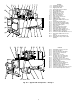
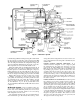

19XL FRONT VIEW
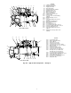
19XL REAR VIEW
Fig. 2A — Typical 19XL Components — Design I
LEGEND
1—Unit-Mounted Starter
2—Refrigerant Filter Drier
3—Rigging Guide Bolt
4—Refrigerant Moisture Indicator
5—Motor Sight Glass
6—Refrigerant Motor Drain
7—Oil Filter Access Cover
8—Refrigerant Oil Cooler
9—Oil Level Sight Glasses
10 — Guide Vane Actuator
11 — Typical Flange Connection
12 — Control Center
13 — ASME Nameplate, Cooler
14 — Take-Apart, Rabbet Fit Connector
(Lower)
15 — Refrigerant Charging Valve
16 — Cooler Refrigerant Isolation Valve
17 — Cooler Pressure Schrader Fittings
18 — Oil Drain/Charging Valve
19 — Power Panel
20 — Retro-Fit, Rig-in-Place Beams
21 — Typical Waterbox Drain Port
22 — Take-Apart, Shell Leveling Feet
23 — Cooler Return-End Waterbox Cover
24 — ASME Nameplate, Condenser
25 — Condenser Return-End Waterbox Cover
26 — Take-Apart, Rabbet Fit Connector
(Upper)
27 — Protective Truck Holddown Lugs
28 — Refrigerant Cooling Isolation Valve
(Hidden)
LEGEND
29 — Pumpdown System Connection
30 — Cooler Relief Valves
31 — Chiller Identification Nameplate
32 — Cooler Pressure Transducer
33 — Suction Elbow
34 — Transmission Vent Line
35 — Discharge Pressure Switch and
Discharge Pressure Transducer
36 — Condenser Isolation Valve
37 — Low-Voltage Access Door, Starter
38 — Medium-Voltage Access Door, Starter
39 — Amp/Volt Gages
40 — Refrigerant Supply Sump
41 — Condenser Pressure Transducer
42 — Liquid Seal Float Chamber
43 — ASME Nameplate, Float Chamber
44 — Condenser Relief Valves
45 — Condenser In/Out Temperature Sensors
46 — Cooler In/Out Temperature Sensors
6