30AWH004HB/30AWH006HB/30AWH008HB/30AWH012HB/30AWH015HB 30AWH004XB/30AWH006XB/30AWH008XB/30AWH012XB/30AWH015XB 30AWH004NX/30AWH006NX/30AWH008NX/30AWH012NX/30AWH015NX SERVICE MANUAL Engineering Department of Italy November, 2010 SM_30AW.
TABLE OF CONTENTS Section Contents 1 2 3 4 5 6 7 8 Page 1.1 Unit specifications ------------------------------------------------------------------------- 2 1.2 Dimension ----------------------------------------------------------------------------------- 5 2.1 General precautions for safety---------------------------------------------------------- 7 2.2 R-410A ---------------------------------------------------------------------------------------- 7 2.
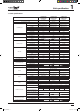
Unit specification 1 1.1 Unit specifications 30AWH004HB 30AWH004XB 30AWH004NX AIR/WATER INVERTER HEAT PUMP MODEL NAME TYPE ELECTRICAL (V-Ph-Hz) TYPE COMPRESSOR REFRIGERANT CHARGED LIQUID RECEIVER REFRIGERANT CONTROL PMV MAKER MODEL Nominal Output kW POLE CAPACITY Btu/h EER Btu/hW kg Manufacturer Volume (in l) Pulse Motor Valve Manufacturer Model W*H*D (mm) OUTDOOR COIL FAN UNIT SYST.RUNNING CURRENT SYST.
MODEL NAME TYPE ELECTRICAL (V-Ph-Hz) TYPE COMPRESSOR REFRIGERANT CHARGED LIQUID RECEIVER REFRIGERANT CONTROL PMV MAKER MODEL Nominal Output kW POLE CAPACITY W - Btu/h EER Btu/hW kg Manufacturer Volume (in l) Pulse Motor Valve Manufacturer Model W*H*D (mm) OUTDOOR COIL FAN UNIT SYST.RUNNING CURRENT SYST.POWER INPUT INSTALLATION FUSE OUTER DIMENSION TOTAL WEIGHT kg PIPING PUMP 2*8 2*(6+1) 7-LSW/7 13-LSW/9,52 FIN PITCH (FPI) 1.41 (18) 1.
Unit specification 1 1.2 Dimensions 30AWH 004 006 008 012 015 A 908 908 908 908 908 B 821 821 821 1363 1363 C 326 326 326 326 326 D 350 350 350 350 350 E 87 87 87 174 174 5 SM_30AW.
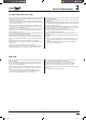
General Informations 2 Precautions for safety Ensure that all Local, National and International regulations are satisfied. t 3FBE UIJT i13&$"65*0/4 '03 4"'&5:w DBSFGVMMZ CFGPSF *OTUBMMBUJPO t 5IF QSFDBVUJPOT EFTDSJCFE CFMPX JODMVEF UIF JNQPSUBOU JUFNT regarding safety. Observe them without fail. t "GUFS UIF JOTUBMMBUJPO XPSL QFSGPSN B USJBM PQFSBUJPO UP DIFDL GPS any problem. Follow the Owner’s Manual to explain how to use and maintain the unit to the customer.
General Informations 2 2.1 General precautions for safety t "TL BO BVUIPSJ[FE EFBMFS PS RVBMJöFE JOTUBMMBUJPO QSPGFTTJPOBM UP JOTUBMM maintain the heat pump. Inappropriate installation may result in water leakage, electric shock or fire. t 5VSO Pò UIF NBJO QPXFS TVQQMZ TXJUDI PS CSFBLFS CFGPSF BUUFNQUJOH BOZ FMFDUSJDBM XPSL .BLF TVSF BMM QPXFS TXJUDIFT BSF Pò 'BJMVSF UP EP so may cause electric shock.
General Informations 2 2.3 Electrical connections All electrical connections are the responsibility of the installer. DANGER CAUTION Electrical shock can cause severe personal injury or death. These operations are carried out by qualified personnel only. t $POOFDU UIF DPOOFDUJOH DBCMF DPSSFDUMZ *G UIF DPOOFDUJOH DBCMF JT connected in a wrong way, electric parts may be damaged.
Installation 3 Installation location INSTALLATION t " MPDBUJPO XIJDI QSPWJEFT B TVóDJFOU TQBDF BSPVOE UIF VOJU t " MPDBUJPO XIFSF UIF PQFSBUJPO OPJTF BOE EJTDIBSHFE BJS BSF OPU disruptive to your neighbours. t " MPDBUJPO UIBU JT OPU FYQPTFE UP B TUSPOH XJOE t " MPDBUJPO UIBU EPFT OPU CMPDL B QBTTBHF t 8IFO UIF VOJU JT JOTUBMMFE JO BO FMFWBUFE QPTJUJPO CF TVSF UP TFDVSF JUT feet.
Installation 3 Minimum clearances Obstacle at rear side Upper side is free Obstacles at both right and left sides.
3 Installation Minimum clearances Obstacles at both front and rear sides Standard installation Open the upper side and both right and left sides. The height of obstacle at both front and rear side, should be lower than the height of the outdoor unit.
3 Installation 3.2 Preliminary operations 150 600 150 430 365 400 15 mm or less Knockout hole Drain nipple mounting hole t Before installation, check strength and horizontality of the base so that abnormal sound does not generate. According to the dimensions and clearances, fix the base firmly with the anchor bolts (Anchor bolt, nut: M10 x 2 pairs).
3 Installation 3.3 Water connections 3.3.1 Hydronic module The 30AWH__H units are equipped with an integrated hydronic module that allows fast installation with the aid of a few external components. The 30AWH__X and 30AWH__NX units, on the other hand, do not have a circulation pump and expansion vessel. For this reason, they must be provided outside. In any case, all the necessary protections and valves are to be inserted in the water circuit inside the unit.
3 Installation 30AWH__X , 30AWH__NX integrated water circuit 2 1. 2. 3. 4.
Installation 3 3.3.3 Typical hydraulic circuit diagrams Hydraulic circuit diagrams for 30AWH___H 3 1 2 6 4 9 7 3 8 1 5 1. 2. 3. 4. 5. TIVU Pò WBMWFT line filter for water (10 mesh/cm^2) pressure gauges filling valve system drain valve (at the lowest points of the circuit) 6. 7. 8. 9. air flushing valve (in the highest parts of the circuit) 3-way valve sanitary water accumulation tank inside system Hydraulic circuit diagrams for 30AWH___X and 30AWH___NX 3 11 3 1 6 2 10 4 9 7 8 1 5 1. 2.
3 Installation 3.3.
3 Installation 3.3.6 Circulating water Pump (only H version) Water flow setting Pump Speed Setting procedure: The best speed setting will provide adequate circulation and provide UIF DPSSFDU øPX BOE SFUVSO UFNQFSBUVSF EJòFSFOUJBMT 5IJT XJMM BDIJFWF NBYJNVN FDPOPNZ BOE FóDJFODZ 1. Set the speed selector to minimum (one) Speed selector 2. Open all thermostatic or manual radiator valves to maximum 3. Set any room thermostatic controls to maximum 4. Start up system and pump should start 5.
Installation 3 3.3.8 Water loop charging, system cleaning and Water Characteristics Charge the water loop, with water, until the pressure on the hydro unit reads 0.15MPa (1.5bar ) Setting NUI Code104 (installation mode) = 1 water pump is forced on. Loosen the cap of the air purge valve located on the top of back up heater to purge air from the water circuit. If air remains in the system the system will not operate correctly.
3 Installation 30 AWH Unit l/s 004 006 008 012 015 0,20 0,28 0,33 0,58 0,69 Nominal water flow Std Water loop content for 30AWH___H units Min l 14 21 28 42 49 Max l 65 65 65 95 95 Max water loop pressure Max kPa 300 300 300 300 300 Filling water pressure Min kPa 120 120 120 120 120 Max elevation 30AW upper Max m 20 20 20 20 20 Pipe water content Internal Diameter Outer diameter 14 mm 16 mm 18 mm 22 mm 28 mm 35 mm 3/8'' Gas 1/2'' Gas 3/4'' Gas 1' Gas 12
Installation 3 3.4 Refrigerant schematics Refrigerant Circuit N° Component N° Component 0 4-way valve 9 TR sensor 1 TS sensor 10 Liquid tank 2 Check joint 11 Pulse Motor Valve 3 Accumulator 12 Distributor 4 Muffler 13 TE sensor 5 TD sensor 13* TL sensor (only 015) 6 DC twin rotary compressor 14 Propellor fan 7 BPHE 15 TO sensor 8 Muffler 16 Heat exchanger 20 SM_30AW.
4 Electrical connections All field electrical connections are the responsibility of the installer. WARNING Make water connections before electrical connections. Make ground connection prior to any other electrical connections 30AWH Unit Power supply 004_ 006_ V- ph - Hz 008_ 012_ 015_ 230 - 1 -50 Allowable Voltage Range V Maximum power drawn kW 2 2.3 2,7 5.1 5.
Electrical connections 4 4.
Electrical connections 4 Terminal Block NX Version 33AW-CS1 Remote control CWGY 23 13 14 2415 1 2 3 6 7 8 21 22 33AW-RC1 Remote control HTG/CLG ON/OFF 1 N N 2 L3 10 4 20 5 12 6 7 4 19 8 9 10 13 11 14 12 15 Sanitary Input 3 Ways valve External Pump Bus RS 485 Defrost signal or air temperature reached signal Alarm and defrost status 4.1.1 Sanitary hot water The 30AWH units drive a 3-way valve (7) to manage a sanitary water accumulation tank.
Electrical connections 4 4.1.2 External heat source An External Heat Source can be driven by Aquasnap Plus. For this feature is necessary install 33AW-CS1 interface Procedure to install an External Heat Source 1. Connect electrically EHS to N and 4 terminals to a relay that drives EHS 2. Configure parameter 106 through 33AW-CS1 interface (1 for EHS) 3. Configure outdoor temperature limits (parameter 148 and 150).
Electrical connections 4 4.1.4 Silent/night mode Silent/night mode is a system setting to limit maximum AQUASNAP noise level. Noise level is reduced limiting maximum compressor frequency. With the contact closed, the unit will operate with a maximum frequency lower than the standard one, otherwise it will operate in standard mode. &H SFEVDJOH BU NBY DPNQSFTTPS GSFRVFODZ NBYJNVN OPJTF MFWFM JT reduced of 3dBA Short-Cut to Frequency reduction Mode 1.
30AWH__H Signal Limits 33AW-CSI Installation Menu Code 23 - 24 Input (NTC 3kΩ @25°C) N.A. 126 Sanitary Water Request 13 - 15 Input (contact switch quality >25mA@12V) N.A. 153 Maximum Frequency Reduction Compressor 13 - 14 Input (contact switch quality >25mA@12V) N.A. 5-6. 3-way valve 10 - 18 - N Output 230Vac (18-N: Power Suply, 10:Signal) 1 ph ~ 230V, 2A N.A.
4.2 Applications Heating Applications External heat source Space heating LWT 55°C Sanitary hot water Mid temp radiator LWT 45°C 60°C 33AW-CS1 INTERFACE Heat pump outdoor unit LWT 35°C Water temperature range produced by AQUASNAP air to water heat pump 20-60°C Under floor heating Humidifier 55°C Sanitary hot water Mid temp radiator 60°C 45°C 33AW-CS1 INTERFACE 35°C Under floor heating Heat pump outdoor unit 27 SM_30AW.
Electrical connections 4 Cooling Applications 4.3 Range Description (Systems capacity) HEATING EWT-LWT OAT 30-35°C 7/6°C COOLING 40-45°C 7/6°C 23-18°C 35°C 12-7°C 35°C Capacity kW COP W/W Capacity kW COP W/W LWA [dB(A)] Capacity kW EER W/W Capacity kW EER W/W LWA [dB(A)] 30AWH004HB 4.10 4,05 3.90 3.2 62 4.90 4.05 3.30 2.91 64 30AWH006HB 5.80 4.20 5.80 3.01 62 7.00 3.61 4.70 2.91 64 30AWH008HB 7.20 3.91 7.40 3.16 64 7.80 3.90 5.80 2.91 65 30AWH012HB 11.
Electrical connections 4 4.4 Wiring diagrams Inverter control size 004HB 29 SM_30AW.
Electrical connections 4 GMC control size 004HB 30 SM_30AW.
Electrical connections 4 Inverter control size 004XB 31 SM_30AW.
Electrical connections 4 GMC control size 004XB 32 SM_30AW.
Electrical connections 4 Inverter control size 006HB 33 SM_30AW.
Electrical connections 4 GMC control size 006HB 34 SM_30AW.
Electrical connections 4 Inverter control size 006XB 35 SM_30AW.
Electrical connections 4 GMC control size 006XB 36 SM_30AW.
Electrical connections 4 Inverter control size 006NX 37 SM_30AW.
Electrical connections 4 GMC control size 006NX 38 SM_30AW.
Electrical connections 4 Inverter control size 008HB 39 SM_30AW.
Electrical connections 4 GMC control size 008HB 40 SM_30AW.
Electrical connections 4 Inverter control size 008XB 41 SM_30AW.
Electrical connections 4 GMC control size 008XB 42 SM_30AW.
Electrical connections 4 Inverter control size 008NX 43 SM_30AW.
Electrical connections 4 GMC control size 008NX 44 SM_30AW.
Electrical connections 4 Inverter control size 012HB 45 SM_30AW.
Electrical connections 4 GMC control size 012HB 46 SM_30AW.
Electrical connections 4 Inverter control size 012XB 47 SM_30AW.
Electrical connections 4 GMC control size 012XB 48 SM_30AW.
Electrical connections 4 Inverter control size 012NX 49 SM_30AW.
Electrical connections 4 GMC control size 012NX 50 SM_30AW.
Inverter control size 015HB 51 SM_30AW.
GMC control size 015HB 52 SM_30AW.
Inverter control size 015XB 53 SM_30AW.
GMC control size 015XB 54 SM_30AW.
Control management 5 Inverter controller GMC controller 30AWH012_ 30AWH015_ 30AWH004_ 30AWH006_ 30AWH008_ Wired remote (RC1) Code: 33AW-RC1_ Wired remote (CS1) Code: 33AW-CS1_ 55 SM_30AW.
5 Control management 5.1 Introduction USER INTERFACES GMC CONTROL INVERTER CONTROLLER Users can select the desired operating NPEF UISPVHI EJòFSFOU SFNPUF DPOUSPMMFST Control is based on the GMC platform developed by Carrier. For the 30AWH AquaSnap PLUS inverter chiller / heat pump a new GMC board has been developed as well as new algorithms have been implemented. The GMC control elaborates the request from the user interface and translates it into a message for the chiller unit control.
Control management 5 When power supply is reset When a unit is powered up, depending on its Auto Start configuration, it will start up with its last operating parameters, or OFF Mode. The EEPROM is available for saving the operating environment of the control in the event of a power-reset condition. If not configured for auto start, at the power up the system will remain in OFF Mode. All the NUI codes will be restored on a power up condition.
Control management 5 Operating mode selection The operating mode is selected based on the command chosen by the remote control. Cooling Mode Depending by the system configuration and when the operating mode is cool, the system could operate as follows: With Comfort NUI (CS1). With SUI (RC1) / Dry inputs. The WSP (Water Set Point) will be defined as follow: - Fixed WSP: as per the appropriate variable value (Standard and Eco) - Climatic Curve depending by OAT (see the controls manuals and the paragraph 7.
Control management 5 Dehumidifier activation (X and H terminal block pins 11 – N) External dehumidifier source is based on NUI Relative Humidity value, (For this feature is necessary install 33AW-CS1 interface). Two codes shall be accesses through NUI: Code 108: It is for defining availability of external dehumidifier. 1 = Alarm or Defrost 2 = External Dehumidifier activation Code 107: - It is Relative Humidity Limit value to activate the heat source.
Control management 5 High Temperature Protection When the water starts to get to hot, this is a sign that the pressure in the system is increasing. Certain actions are taken to decrease the pressure. Tw: Max(Actual Water Temperature Entering, Actual Water Temperature Exiting) Tr: Actual Refrigerant Temperature Fr(n): real frequency from the chiller unit Fhmin: minimum compressor speed allowed in heating Tw Compressor OFF 62 °C M 61 °C L 60 °C N While in Zone N or L the frequency can’t increase.
5 Control management Unit Status and Defrost output or Tair Setpoint status Based on the NUI code 147 set-up, the Output J7 Pin 2 (N-5 on the terminal block) could play for one of these Functions: - ALARM: The intent of this output is to point out the alarm condition. This signal could be used by an external control to verify if the Unit is able to operate with the requested function.
Control management 5 Backup External Heat Source functionality (X and H terminal block pins 5 – N) This functionality is valid when user mode is HEATING MODE. Between pins 5 and N of terminal strip (see paragraph 4.1) an output is available (1 ph ~ 230V, 2A max) to activate a backup external heat source (such as Electric Heater or Boiler). This functions is activates using the NUI.
5 Control management System Diagnostics The control contains diagnostic tests to verify the integrity of the system. The On Board LED is located on the circuit board. It is used to display normal operation status and diagnostic fault code information. The control board status LED will flash at a rate of one (1) second ON and one (1) second OFF while the control is operating normally. When in a diagnostic fault code, it will blink out the fault code. Once a failure occurs, the system is considered failed.
Control management 5 Discharge temperature release control 1) This function controls the compressor frequency, when the discharge temperature has increased due to max load condition or during PMV control. It subdivides the frequency control up to a unit of 0.6 Hz to stabilize the cycle. 2) When the discharge temperature is detected in an abnormal stop zone, the unit stops the compressor and restarts it after 2 minutes, 30 seconds (time guard).
Control management 5 Outdoor fan control Allocations of fan tap revolutions FAN TAP W1 W2 W3 W4 W5 W6 W7 W8 W9 WA WB WC WD WE WF WG 30AWH004 0 200 280 320 350 380 420 460 500 530 560 580 600 600 600 600 30AWH006 0 200 250 300 350 400 450 500 550 580 600 600 600 600 600 600 30AWH008 200 240 280 310 350 380 420 450 490 520 580 630 680 680 680 - 30AWH012 Higher fan 250 260 270 280 330 380 430 480 530 590 650 700 730 750 - -
Control management 5 The output frequency and the output voltage are controlled by AC current detected on the P.C. board. The max current value of the inverter are shown in table below. TE(oC) MAX 46 +30 rpm/20 sec. 37 Hold zone 34 -30 rpm/20 sec. 20 MIN TO TO < 5C 5 <= TO < 10C 25 <= TO TO error MIN W1 W2 10 <= TO < 15C 15 <= TO < 20C 20 <= TO < 25C W3 W4 W5 WA W1 MAX W6 W8 WA WC WE WE WE 015 size 1.
Control management 5 2) Heating fan control 004-006 sizes The blowing air volume at the outdoor unit side is controlled as follow: 1. When strong wind blows at outdoor side, the operation of heat pump continues with the fan motor stopped. 2. Whether the fan is locked or not detected, and the operation of heat pump stops and an alarm is displayed if the fan is locked. 3.
Control management 5 Coil heating control (compressor warm up process) 5IJT DPOUSPM SPVUJOF NBJOUBJOT TVóDJFOUMZ IFBUFE UIF DPNQSFTTPS TUPQQFE CZ QPXFSJOH PO UIF XJOEJOHT JOTUFBE PG B crankcase heater. The control purpose is to prevent slackness of refrigerant inside the compressor. 5P BWPJE DPNQSFTTPS EBNBHJOH EVSJOH UIF JOTUBMMBUJPO UFTU NPEF PS BGUFS MPOH DPNQSFTTPS Pò UJNF JU T BEWJTFE UP TUBSU the system when the control has interrupted the compressor warm up process. 3.
5 Control management High-Pressure suppression TE control 1. This control routine suppresses that pressure which becomes abnormally too high during the cooling operation. TE: Entering *U TUPQT UIF DPNQSFTTPS JG 5& Ż ¡$ BOE DPVOU PO UIF FSSPS DPVOUFS "GUFS NJOVUFT TFDPOET PG DPNQSFTTPS Pò UJNF (in Heat guard) if TE < 67°C, the compressor is enable to restart.
Control management 5 Defrost control (Only in heating opearation) In heating operation, defrost operation is performed when TE sensor temperature satisfies any condition in A zone to D zone.
6 Diagnostic 6.1 Diagnostic 6.1 Inverter alarms 6.1.1 Error codes 30AWH012 only t 8IFO DPNQSFTTPS DBTF UIFSNPTUBU PQFSBUFT UIF DPNNVOJDBUJPO JT interrupted on the serial circuit. If the case thermostat operation happens continuously, a serial communication error occurs because of a serial message has been sent. t #FGPSF B DIFDL DPOöSN FBDI CJU PG UIF %*1 TXJUDI JT TFU UP 0'' QPTJUJPO Troubles of the unit can be diagnosed by LED indications on the cycle control P.C. board of the unit.
Diagnostic 6 6.1.2 Error codes 30AWH015 only c) If there is an error, any of LED D800 to D804 goes on. (Display 1) d) When pushing the pushdown button switch SW800 for approx. 1 second, the display is exchanged. (Display 2) e) When pushing SW800 again or after 2 minutes, the status returns to that of Display 1. The error which is generating at present and the latest error (Latest error information including present) can be confirmed by lighting LED D800 toD804 on the control P.C. board.
6 Diagnostic The values detected by the controller, such as temperature sensor or current value are simply confirmed.
Diagnostic 6 6.2 GMC alarm codes BOE UIBO SFNBJOT Pò BHBJO GPS TFDPOET *G UIF FSSPS DPEF IBT EJHJUT the flashing is interrupted for 2 seconds between the first and second digits. &YBNQMF FSSPS -&% Pò GPS TFDPOET øBTIFT BU B GSFRVFODZ PG )[ 0ò GPS TFDPOET øBTIFT BU B GSFRVFODZ PG )[ 0ò GPS TFDPOET 5IF DZDMF SFQFBUT VOUJM UIF -&% UVSOT Pò CFDBVTF UIF QSPCMFN JT resolved or if an error with higher priority occurs. There is a LED on the GMC board that displays any board errors.
Diagnostic 6 NOTE: Unit status OFF means that unit immediately stops. 6.
Diagnostic Description Reference Type Units 220V min 220V Max EHS/defrost J7 Pin 3 Relay Voltage 198 264 Alarm Status for SUI (Low and High flashing as per on board led timing) J11 Pin5 Alarm + defrost status/ Dehumidifier J7 Pin 4 3 Way Valve Open collector Relay J4 Pin 5 Relay Amps 0.3 2 Power Factor 0.85 0.98 Freq 48 52 Voltage 10 12 Amps 0.01 0.012 Voltage 198 264 Amps 0.3 2 Power Factor 1 1 Freq 48 52 Amps 0.01 0.012 Voltage 198 264 Amps 0.
Diagnostic 6 6.4 Troubleshooting Fault code 3 – Enter Water Temperature sensor fault Is the TA sensor correctly connected? (See Wiring Diagrams) NO Correctly connect the TA Sensor YES Are the resistance characteristics of the temperature sensor TA normal?* NO Replace defective TA Sensor * Check resistance curve YES Check indoor P.C.
Diagnostic 6 Fault code 6 – Loss communication to NUI control Are the connections of NUI and GMC board correct? NO Check and correct the connections YES Are all cables and connectors correctly fitted? NO Check cabling between NUI and GMC board YES Check GMC Board - if defective, replace Check NUI error - if defective, replace Fault code 7 – NUI control Room sensor fault Is the sensor correctly connected? NO Correctly connect the Sensor NO Replace defective Sensor YES Are the resistance char
Diagnostic 6 Fault code 9 – Flow Switch error / Water Pump NO NO Flow switch is connected to board? Pump rotates? Perform air vent YES Connect flow switch connector to board YES YES Excess air noise comes from inside the pump? Built-in pump is connected to board? NO NO Connect pump connector to board YES Flow switch is normal? NO Replace flow switch YES Chattering noise comes from flow switch? Replace pump YES NO Pump stops 2-3 minutes after its rotation started? YES NO Dirt clogging
Diagnostic 6 Fault code 13 – Loss communication to RS485 Are the connections correct? (See Wiring Diagrams) NO Check and correct the connections NO Check cabling YES Are all cables and connectors correctly fitted? YES Check GMC Board - if defective, replace Fault code 14 – Loss of signal from inverter board Are the connections of inverter board and GMC board correct? (See Wiring Diagrams) NO Check and correct the connections YES Are all cables and connectors correctly fitted? NO Check cablin
Diagnostic 6 Fault code 17 – Inverter Air sensor fault NO Is the sensor correctly connected? (See Wiring Diagrams) Correctly connect the Sensor YES Are the resistance characteristics of the temperature sensor normal?* NO Replace defective Sensor YES Check Inverter board - replace if defective *Check resistance table Fault code 18 – G - Tr Short-circuit protection Is the power supply (line) voltage correct? NO Correct the power supply voltage YES Are the inter-connections and cabling correct?
Diagnostic 6 Fault code 21 – Inverter current sensor fault Is the power supply cabling and sensor cabling correct? (See Wiring Diagrams) NO Check and correct cable NO Correctly connect the Sensors NO Replace defective Sensors YES Check inverter board Fault code 22 – Heat exchanger Sensors TE/TS Are the sensors correctly connected? (See Wiring Diagrams) YES Are the resistance characteristics of the temperature sensors normal?* YES Check Inverter board - replace if defective *Check resistance
Diagnostic 6 Fault code Fault code 24 – Outdoor fan motor error– Compressor lock Are connectors CN300, CN301, CN302 and CN303 connected correctly?* NO YES Is it possible to freely rotate the fan with hands when CN300, CN301, CN302 & CN303 are disconnected?* NO YES Normal resistance value between leads: Between (1) (Red lead) and (2) (White lead) Between (2) (White lead) and (3) (Black lead) Between (3) (Black lead) and (1) (Red lead) on wind ing connector CN301 & CN303* NO YES Normal resistance v
Diagnostic 6 Fault code 27 – Compressor lock NO I s the power suppl y vol tage correct? C orrect power supply voltage YES NO Are the connections of cables and connectors correct? Check and correct the cabling & connections YES Is the compressor functional? NO Has there been a refrigerant leak? YES NO Compressor lock - replace YES Does the electronic expansion valve operate normally? NO Check TE and TS Sensors, replace if defective Check expansion valve, replace if defective YES Check GMC &
Diagnostic 6 Fault code 29 – Compressor break down Is the power supply voltage normal? NO Correct the power supply voltage YES Does and overload condition exist? YES Delete the cause of overload NO Check and correct circuit cables NO Is the current detected by the current sensor normal? YES Check P.C. boards, if defective replace. 85 SM_30AW.
Diagnostic 6 Fault code 14 – High temperature release NO Does the unit operate? YES NO Are the inter-connecting cables correctly wired? Correct inter-connecting cabling YES NO Are the connectors correctly located? Check P.C.
6 Diagnostic 6.4.
Diagnostic 6 For 004, 006, 008, 012, 015 sizes LWT,EWT sensors 100 2 90 1.8 80 1.6 70 1.4 60 Resistence [k Ω] 50 T<50°C 40 1.2 30 0.6 20 0.4 10 0.2 1 Resistence [kΩ ] T>50°C 0.
Diagnostic 6 6.4.1 Resistance values of main components 4 6 8 12 15 Ω T ref [°C] Ω T ref [°C] Ω T ref [°C] Ω T ref [°C] Ω T ref [°C] PMV 46±4 25 46±4 25 46±4 20 46±3 20 46±3 20 4 Way 1795±150 25 1795±150 25 1765±150 24 1774±150 24 1489±150 22 22±2 25 22±2 25 22.4±2 24 35.2±2 24 17.9±2 22 Fan motor 21.9±2 25 21.9±2 25 22.6±2 24 34.8±2 24 18.9±2 22 21.9±2 25 21.9±2 25 22.6±2 24 35±2 24 17.
Carrier interfaces 7 The AquaSnap PLUS can use the following user interfaces: ESZ DPOUBDUT UIF "RVB4OBQ 1-64 "8 3$ SFNPUF DPOUSPMMFS the 33AW-CS1 Comfort Series programmable thermostat the Carrier Dealer Service Tool. 7.1 Dry contacts control 90 SM_30AW.
Carrier interfaces 7 7.2 33AW-RC1 user interface WARNING: #FGPSF JOTUBMMJOH UIF SFNPUF DPOUSPMMFS UVSO Pò BMM QPXFS UP UIF VOJU UIBU will supply power to the remote controller. Electrical shock can cause personal injury or death. - Open the remote controller rear mounting base to expose mounting holes. The base can be removed to simplify mounting (snap apart carefully at hinge to separate mounting base from remainder of the remote controller).
Carrier interfaces 7 7.2.
Carrier interfaces Carrier’s NUI series programmable user interface is wall-mounted, low-voltage user interface which maintains room temperature by controlling the operation of a heating and/or air conditioning system. i)FBU QVNQw i "JS DPOEJUJPOFSw BOE i)FBU POMZw BSF BWBJMBCMF XJUI UIF present versions. A variety of features are provided including separate heating and cooling set-points, keypad lockout, backlighting, and builtin installer test etc.
Carrier interfaces 7 7.3.1 Main functions User functionality (comfort): t 0OF UPVDI JOUFSGBDF UP TFMFDU EJòFSFOU SPPN UFNQFSBUVSF TFU t QPJOU NPEF )PNF 4MFFQ "XBZ t %JTQMBZ PG t $MJNBUJD EJTQMBZ 3PPN 5 0"5 5 BOE 3PPN 3) t 5JNF BOE EBZ PG UIF XFFL t )FBU TPVSDF )FBU 1VNQ /JHIU 4)8 &)4 t .
7 Carrier interfaces 7.3.3 Control buttons Mode Up & down Hold Zone Done Home Sleep Away Days Period Day/hour/min Start time For more details refer to specific manuals. 7.3.4 Codes table Code Nr. Name 1 MODE 2 HOME ANTIFREEZE 3 HOME ANTIFREEZE TEMPERATURE 4 ADJUST WATER TEMPERATURE SET-POINT 5 6 VALUE RANGE DESCRIPTION STANDARD Min Max - - 0ò 1 2 1. Disable 6°C 12°C 6°C This code is use to adjust the water set-point changing the setted climatic curve.
Carrier interfaces Code Nr. Name VALUE RANGE DESCRIPTION Min Max STANDARD 11 ( ) OUTDOOR TEMPERATURE This code displays the Outdoor Air Temperature. The valid OAT value is used with this priority: 1. OAT from GMC thermistor (if it is installed) 2. OAT from inverter, read by TO sensor. -30°C 90°C - 12 ( ) GMC OUTDOOR AIR TEMPERATURE This code displays the Outdoor Air Temperature read by GMC thermistor.
7 Carrier interfaces Code Nr. Name 108 ALARM-DEFROST OR HUMIDITY SELECTION 109 FROST DELTA SET-POINT 110 RESET COMPRESSOR RUN-TIME 111 ( ) FLOW SWITCH STATUS VALUE RANGE DESCRIPTION STANDARD Min Max 1 2 2 This code is use to set the frost delta set-point used by the Anti frost protection logic as per algorithm. 0°C 6°C 1°C This code is use to reset the compressor timer to zero. No yes No - - - 0 12 0 This code is use to set the fixed heating water set-point.
Carrier interfaces Code Nr. Name VALUE RANGE DESCRIPTION STANDARD Min Max This code displays the real compressor frequency - - - 134 ( ) REAL FREQUENCY 135 ( ) COMPRESSOR RUNTIME This code displays the working on hours of the compressor.. - - - 136 ( ) CDU CAPACITY This code displays the nominal heat pump capacity [kW].
7 Carrier interfaces Code Nr. Name 154 EXTERNAL HEAT SOURCE STATUS 155 MAIN WATER PUMP LOGIC VS EHS STATUS 156 TRACE HEATER / ADDITIONAL WP LOGIC 157 ADDITIONAL WATER PUMP LOGIC 158 DELTA AIR SET-POINT 302 UNIT CONFIGURATION VALUE RANGE DESCRIPTION This code is use to define the external heat source status when EHS is activated and OAT < temperature value set in Code 148: 0.
Carrier interfaces 100 SM_30AW.
Carrier interfaces 7 Custom curves Parameters 112 and 117 set to 0 allows to load in the control a custom climatic curve. Below figures show which parameter of installer configuration table need to be set to create customized heating and cooling curves. 1. 2. 3. 4. 5. 6. 7. 8.
Maintenance 8 8.1 Refrigerant charge check IMPORTANT: All maintenance operations must be performed by qualified personnel. This check becomes necessary after any refrigerant leak or after replacement of the compressor. The best method to correctly charge refrigerant is to completely empty the refrigerant circuit using refrigerant recovery equipment. Then charge the exact quantity of refrigerant according to the data shown on the unit nameplate. R-410A systems must be charged with liquid refrigerant.
8 Maintenance 8.3 Replacement of the main parts N° Exchange parts name Work procedure (IMPORTANT: Ensure gloves are worn at all times to avoid risk of injury) Common procedure t Detachment 4UPQ PQFSBUJPO PG UIF IFBU QVNQ BOE UVSO Pò switch of the breaker. 3FNPWF UIF GSPOU QBOFM 45 1 t QDT After unscrewing the screws, remove the front panel while drawing it downward. 3. Remove the power cable from cord clamp and terminal.
Maintenance N° Exchange parts name (4) Inverter assembly Work procedure (IMPORTANT: Ensure gloves are worn at all times to avoid risk of injury) 8 Remarks Inverter cover 1. Perform the works from 1 to 4 of (1) and (2) . WARNING 'PS NJOVUF BGUFS UIF QPXFS JT UVSOFE Pò EP OPU disassemble the inverter to prevent an electric shock. Perform discharging by connecting the discharging resistance or plug of soldering iron to + , – terminals of the C10 too 13 electrolytic capacitor (760μF) of P.C. board.
Maintenance N° Exchange parts name Work procedure (IMPORTANT: Ensure gloves are worn at all times to avoid risk of injury) (6) Reactors 1. Perform the works from 1 to 4 of (1) and (2). 2. Remove the inverter assembly item (4). 3. Remove the reactors’ connectors. 5BLF Pò UIF TDSFXT 45 1 t QDT öYJOH the reactor to the partition plate. 5. Pull the reactor upward and detach it from the partition plate. 6. Replace the fail reactor with a new one.
Maintenance N° Exchange parts name Work procedure (IMPORTANT: Ensure gloves are worn at all times to avoid risk of injury) (9) Compressor Perform the works from 1 to 4 of (1) and (2), (3), (4), (6), (7). 1. Discharge refrigerant gas.
Maintenance N° Exchange parts name Work procedure (IMPORTANT: Ensure gloves are worn at all times to avoid risk of injury) (11) Pulse modulating valve (PMV) coil t %FUBDINFOU 1. Perform the works from 1 to 4 of (1) and (3). 2. Hold outside of the coil by hands and turn it while lifting upward. 5IF öYJOH IPPLT DPNF Pò UIF öYJOH DPODBWJUJFT BOE then the coil can be removed from PMV body. Remarks t "UUBDINFOU 4.
Maintenance N° Exchange parts name Work procedure (IMPORTANT: Ensure gloves are worn at all times to avoid risk of injury) Water circuit CAUTION: To replace a water circuit part, first close the water supply source valve and the valve of water pipe connected to the unit. 8 Remarks Entering water Flow switch Automatic purge valve Water pump motor Exiting water Water Pump Relief valve Water Drain BPHE (13) (14) Expansion vessel (Only H versions) Relief valve 1.
Maintenance N° Exchange parts name Work procedure (IMPORTANT: Ensure gloves are worn at all times to avoid risk of injury) (15) Automatic purge valve 1. Perform works from 1 to 4 of (1) and (2). 2. Remove the automatic purge valve. IMPORTANT After the automatic purge valve replacement repair, open the water supply source valve and water piping valve to pass water through the hydro unit, and check that the air vent valve connection has no water leakage.
Maintenance N° Exchange parts name Work procedure (IMPORTANT: Ensure gloves are worn at all times to avoid risk of injury) (19) Pump (Only H versions) 1. Perform works from 1 to 4 of (1) and (2). 2. Remove the relative connectors 3. Remove the 2 nuts of the heater connection and the lower side of the pump. 4. Remove the pump pulling it out. 8 Remarks Pump motor Nuts CAUTION: The pump connection uses a liquid packing for water seal.
Maintenance N° Exchange parts name (3) Air-outlet cabinet Work procedure (IMPORTANT: Ensure gloves are worn at all times to avoid risk of injury) 8 Remarks Heat exchanger t %FUBDINFOU 1. Perform the work from 1 to 4 of (1). 2. Remove the screws for the air-outlet cabinet and UIF QBSUJUJPO QMBUF 45 1 t QDT 3. Remove the screws for the air-outlet cabinet and UIF CBTF QMBUF 45 1 t QDT 4.
Maintenance N° Exchange parts name Work procedure (IMPORTANT: Ensure gloves are worn at all times to avoid risk of injury) (5) Cycle PC board (012) 1. Perform the works from 1 to 4 of (1) ,(3) and (4). 2. Remove connectors and lead wires: Connector CN800: Connection with IPDU P.C. board (5P) CN01: Connection with IPDU P.C. board (5P) CN02: Indoor/Outdoor connection terminal block (3P) CN03: Connection with IPDU P.C. board (3P) CN04: Connection with IPDU P.C. board (2P).
Maintenance N° Exchange parts name Work procedure (IMPORTANT: Ensure gloves are worn at all times to avoid risk of injury) (7) Reactors (012) 1. Perform the works from 1 to 4 of (1) and (2). 2. Remove the inverter assembly item (4). 3. Remove the reactors’ connectors. 5BLF Pò UIF TDSFXT 45 1 t QDT öYJOH the reactor to the partition plate. 5. Pull the reactor upward and detach it from the partition plate. 6. Replace the fail reactor with a new one. (8) Control P.C.
Maintenance N° Exchange parts name Work procedure (IMPORTANT: Ensure gloves are worn at all times to avoid risk of injury) (9) Reactor (015) 1. Perform the works from 1 to 4 of (1) and (2). 2. Remove the reactor lead connected to the control P.C. board. CN05 White, CN06 White 3. Cut the bundling band which bundled the compressor lead and fan motor lead. 4. Remove the reactor. (Trust B tight screw, Ø4 × 6, 2 pcs.) 5. Replace the reactor with a new one.
Maintenance N° Exchange parts name Work procedure (IMPORTANT: Ensure gloves are worn at all times to avoid risk of injury) (11) Fan motor 1 Perform the works from 1 to 4 of (1) and (3). 5BLF Pò UIF øBOHF OVU öYJOH UIF GBO NPUPS BOE UIF propeller. Lose the flange nut by turning clockwise. (To tighten the flange nut, turn counter-clockwise.) 3. Remove the propeller fan. 4. Disconnect the connector for fan motor from the inverter.
Maintenance N° Exchange parts name Work procedure (IMPORTANT: Ensure gloves are worn at all times to avoid risk of injury) (13) Liquid receiver 1. Perform the works from 1 to 4 of (1) and (2), (3), (4), (5), (8). 2. Discharge refrigerant gas. 3. Remove the nut fixing the liquid receiver and the partition plate. 3FNPWF UIF QBSUJUJPO QMBUF UBLF Pò TDSFXT GSPN UIF CBTF QMBUF 45 1 t QDT BOE GSPN UIF IFBU FYDIBOHFS 45 1 t QDT 5.
8 Maintenance N° Remarks Work procedure (IMPORTANT: Ensure gloves are worn at all times to avoid risk of injury) (15) Water circuit CAUTION: Remarks Expansion vessel To replace a water circuit part, first close the water supply source valve and the valve of water pipe connected to the unit. Automatic purge valve Entering water Flow switch Exiting water Water drain Water Pump mp (16) Expansion vessel (Only H versions) Relief valve Relie e BPHE BPH Expansion vessel v 1.
N° Remarks (19) Flow switch Work procedure (IMPORTANT: Ensure gloves are worn at all times to avoid risk of injury) Remarks 1. Perform works from 1 to 4 of (1) and (2). 2. Remove the relative connector 3. Remove the flow switch. CAUTION: The flow switch connection uses an O ring for water TFBM #F DBSFGVM OPU UP TDSBUDI UIF 0 SJOH PUIFSXJTF water leakage may occur. Place a flow sensor parallel to the water heat exchanger inlet pipe so that the wire is place on the right side from the front view.
8.4 Periodic Inspection Items Unit Frequency Periodic inspection details Insulation measurement (Power source circuit/ Compressor) Annually Insulation measurement with a mega tester Operation check Annually Hot water supply/ Heating/ Cooling operation check with remote controller. Refrigerant leakage/ Water leakage inspection. Annually Visual inspection and check with a leak tester: No leakage must be found.
Spare Parts 9 For the spare parts refer to specific document. 120 SM_30AW.
SM_30AW.indd 121 -25 -25 -15 -15 121 -5 1.50 2.50 3.50 4.50 5.50 6.50 7.50 COP 40-45 °C -5 1.50 2.50 3.50 4.50 5.50 6.50 7.50 5 5 COP 30-35 °C 15 15 25 25 35 OAT [°C] Max Med Min Frequency 35 OAT [°C] Frequency Max Med Min -25 -25 -15 -15 -5 -5 15 25 35 0.00 1.00 2.00 3.00 4.00 5.00 6.00 7.00 8.00 9.00 10.00 11.00 12.00 0.00 1.00 2.00 3.00 4.00 5 15 CAPACITY [kW] 40-45°C 25 35 OAT [°C] Max Med Min Frequency OAT [°C] Max Med Min 5.
SM_30AW.indd 122 -25 -25 -15 -15 -5 -5 122 1.50 2.00 2.50 3.00 3.50 4.00 4.50 5.00 1.50 2.00 2.50 3.00 3.50 4.00 4.50 5.00 5 COP 55-60 °C 5 COP 50-55 °C 15 15 25 25 OAT [°C] Frequency Max Med Min 35 35 OAT [°C] Frequency Max Med Min -25 -25 -15 -15 -5 -5 0.00 1.00 2.00 3.00 4.00 5.00 6.00 7.00 8.00 9.00 10.00 11.00 12.00 0.00 1.00 2.00 3.00 4.00 5.00 6.00 7.00 8.00 9.00 10.00 11.00 12.
SM_30AW.indd 123 123 35 40 45 45 50 OAT [°C] Frequency 50 12.00 1.00 0.00 2.00 2.00 OAT [°C] 3.00 4.00 0.00 4.00 6.00 5.00 6.00 8.00 10.00 Max Med Min 0 5 10 0 5 10 CAPACITY [kW] 23-18 °C 0.00 7.00 12.00 30 40 8.00 25 35 14.00 30 9.00 COP 23-18 °C 25 16.00 20 20 10.00 15 15 18.00 10 10 1.00 2.00 3.00 4.00 5.00 11.00 5 5 Frequency Max Med Min 6.00 7.00 8.00 CAPACITY [kW] 12-7 °C 20.00 0 0 COP 12-7 °C 22.00 24.00 0.00 2.00 4.00 6.00 8.
SM_30AW.indd 124 -25 -25 -15 -15 5 124 -5 1.50 2.50 3.50 4.50 5.50 6.50 7.50 5 COP 40-45 °C -5 1.50 2.50 3.50 4.50 5.50 6.50 7.50 COP 30-35 °C 15 15 25 25 35 35 OAT [°C] Max Med Min Frequency OAT [°C] Max Med Min Frequency -25 -25 -15 -15 0.00 5 -5 0.00 1.00 2.00 3.00 4.00 5.00 6.00 7.00 8.00 9.00 10.00 11.00 12.00 5 CAPACITY [kW] 40-45 °C -5 1.00 2.00 3.00 4.00 5.00 6.00 7.00 8.00 9.00 10.00 11.00 12.
SM_30AW.indd 125 30AW 14-03-2011 14:47:08 -25 -25 -15 -15 5 -5 1.50 2.00 2.50 3.00 3.50 4.00 4.50 5.00 5 COP 55-60 °C -5 1.50 2.00 2.50 3.00 3.50 4.00 4.50 5.00 COP 50-55 °C 15 15 25 25 35 35 OAT [°C] Max Med Min Frequency OAT [°C] Max Med Min Frequency -25 -25 -15 -15 0.00 5 -5 0.00 1.00 2.00 3.00 4.00 5.00 6.00 7.00 8.00 9.00 10.00 11.00 12.00 5 CAPACITY [kW] 55-60 °C -5 1.00 2.00 3.00 4.00 5.00 6.00 7.00 8.00 9.00 10.00 11.
SM_30AW.indd 126 0 126 -1.00 1.00 3.00 5.00 7.00 9.00 11.00 13.00 15.00 17.00 19.00 21.00 23.00 25.00 0.00 2.00 4.00 6.00 8.00 10.00 12.00 14.00 0 5 5 10 10 15 15 25 30 25 30 COP 23-18 °C 20 20 COP 12-7 °C 35 35 40 40 45 45 OAT [°C] 50 OAT [°C] Max Med Min Frequency 50 Frequency Max Med Min 0 0.00 2.00 4.00 6.00 8.00 10.00 12.00 0.00 1.00 2.00 3.00 4.00 5.00 6.00 7.00 8.
SM_30AW.indd 127 -25 -25 -15 -15 5 127 -5 1.50 2.50 3.50 4.50 5.50 6.50 7.50 5 COP 40-45 °C -5 1.50 2.50 3.50 4.50 5.50 6.50 7.50 COP 30-35 °C 15 15 25 25 35 35 OAT [°C] Max Med Min Frequency OAT [°C] Max Med Min Frequency -25 -25 -15 -15 0.00 5 -5 0.00 1.00 2.00 3.00 4.00 5.00 6.00 7.00 8.00 9.00 10.00 11.00 12.00 5 CAPACITY [kW] 40-45 °C -5 1.00 2.00 3.00 4.00 5.00 6.00 7.00 8.00 9.00 10.00 11.00 12.
SM_30AW.indd 128 30AW 14-03-2011 14:47:12 -25 -25 -15 -15 5 -5 1.50 2.00 2.50 3.00 3.50 4.00 4.50 5.00 5 COP 55-60 °C -5 1.50 2.00 2.50 3.00 3.50 4.00 4.50 5.00 COP 50-55 °C 15 15 25 25 35 35 OAT [°C] Max Med Min Frequency OAT [°C] Max Med Min Frequency -25 -25 -15 -15 0.00 5 -5 0.00 1.00 2.00 3.00 4.00 5.00 6.00 7.00 8.00 9.00 10.00 11.00 12.00 5 CAPACITY [kW] 55-60 °C -5 1.00 2.00 3.00 4.00 5.00 6.00 7.00 8.00 9.00 10.00 11.
SM_30AW.indd 129 129 30 45 50 0.00 1.00 0.00 2.00 2.00 OAT [°C] 3.00 4.00 0.00 4.00 6.00 5.00 6.00 8.00 10.00 12.00 0 0 7.00 Frequency Max Med Min OAT [°C] 8.00 40 50 14.00 35 45 9.00 30 40 16.00 25 35 10.00 COP 23-18 °C 25 18.00 20 20 11.00 15 15 20.00 10 10 1.00 2.00 3.00 4.00 5.00 22.00 5 5 Frequency Max Med Min 6.00 7.00 8.00 12.00 0 0 COP 12-7 °C 24.00 0.00 2.00 4.00 6.00 8.00 10.00 12.00 14.
SM_30AW.indd 130 -25 -25 -15 -15 5 130 -5 1.50 2.50 3.50 4.50 5.50 6.50 7.50 5 COP 40-45 °C -5 1.50 2.50 3.50 4.50 5.50 6.50 7.50 COP 30-35 °C 15 15 25 25 35 35 OAT [°C] Max Med Min Frequency OAT [°C] Max Med Min Frequency -25 -25 -15 -15 0.00 5 -5 0.00 2.00 4.00 6.00 8.00 10.00 12.00 14.00 16.00 18.00 20.00 22.00 24.00 26.00 5 CAPACITY [kW] 40-45 °C -5 2.00 4.00 6.00 8.00 10.00 12.00 14.00 16.00 18.00 20.00 22.00 24.00 26.
SM_30AW.indd 131 30AW 14-03-2011 14:47:17 -25 -25 -15 -15 1.50 5 -5 1.50 2.00 2.50 3.00 3.50 4.00 5 COP 55-60 °C -5 2.00 2.50 3.00 3.50 4.00 COP 50-55 °C 15 15 25 25 35 35 OAT [°C] Max Med Min Frequency OAT [°C] Max Med Min Frequency -25 -25 -15 -15 0.00 5 -5 0.00 2.00 4.00 6.00 8.00 10.00 12.00 14.00 16.00 18.00 5 CAPACITY [kW] 55-60 °C -5 2.00 4.00 6.00 8.00 10.00 12.00 14.00 16.00 18.
SM_30AW.indd 132 132 30 40 45 50 50 Frequency Max Med Min OAT [°C] 0.00 0.00 2.00 2.00 OAT [°C] 4.00 0.00 6.00 4.00 8.00 10.00 6.00 8.00 10.00 12.00 35 45 14.00 30 40 12.00 25 35 14.00 COP 23-18 °C 25 16.00 20 20 18.00 15 15 16.00 10 10 2.00 4.00 6.00 8.00 10.00 12.00 18.00 5 5 Frequency Max Med Min 14.00 16.00 18.00 20.00 20.00 0 0 COP 12-7 °C 20.00 0.00 2.00 4.00 6.00 8.00 10.00 12.
SM_30AW.indd 133 -25 -25 -15 -15 133 -5 1.50 2.50 3.50 4.50 5.50 6.50 7.50 COP 40-45 °C -5 1.50 2.50 3.50 4.50 5.50 6.50 7.50 COP 30-35 °C 5 5 15 15 25 25 35 35 OAT [°C] Max Med Min Frequency OAT [°C] Max Med Min Frequency -25 -25 -15 -15 0.00 5 -5 0.00 2.00 4.00 6.00 8.00 10.00 12.00 14.00 16.00 18.00 20.00 22.00 24.00 26.00 5 CAPACITY [kW] 40-45 °C -5 2.00 4.00 6.00 8.00 10.00 12.00 14.00 16.00 18.00 20.00 22.00 24.00 26.
SM_30AW.indd 134 30AW 14-03-2011 14:47:22 -25 -25 -15 -15 1.50 -5 1.50 2.00 2.50 3.00 3.50 4.00 COP 55-60 °C -5 2.00 2.50 3.00 3.50 4.00 COP 50-55 °C 5 5 15 15 25 25 35 35 OAT [°C] Max Med Min Frequency OAT [°C] Max Med Min Frequency -25 -25 -15 -15 0.00 5 -5 0.00 2.00 4.00 6.00 8.00 10.00 12.00 14.00 16.00 18.00 20.00 5 CAPACITY [kW] 55-60 °C -5 2.00 4.00 6.00 8.00 10.00 12.00 14.00 16.00 18.00 20.
SM_30AW.indd 135 135 0.00 2.00 4.00 6.00 8.00 10.00 12.00 14.00 16.00 18.00 20.00 0.00 2.00 4.00 6.00 8.00 10.00 12.00 0 0 5 5 10 10 15 15 20 20 25 COP 23-18 °C 25 COP 12-7 °C 30 30 35 35 40 40 45 45 50 50 OAT [°C] Frequency Max Med Min OAT [°C] Frequency Max Med Min 0.00 2.00 4.00 6.00 8.00 10.00 12.00 14.00 16.00 18.00 20.00 22.00 24.00 0.00 2.00 4.00 6.00 8.00 10.00 12.00 14.00 16.00 18.00 20.
Additional Informations 11 11.1 Additional information 136 SM_30AW.
Additional Informations 11 11.1 Additional information 137 SM_30AW.
L010129H30-0111 Via R. Sanzio, 9 - 20058 Villasanta (MI) Italy - Tel. 039/3636.1 The manufacturer reserves the right to change any product specifications without notice. November, 2010 Supersedes October, 2008. SM_30AW.