
Service manual


110
30AW
Maintenance
8
N° Exchange
parts
name
Work procedure (IMPORTANT: Ensure gloves are
worn at all times to avoid risk of injury)
Remarks
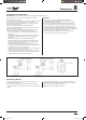
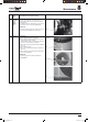
(19) Pump
(Only H
versions)
1. Perform works from 1 to 4 of (1) and (2).
2. Remove the relative connectors
3. Remove the 2 nuts of the heater connection and the
lower side of the pump.
4. Remove the pump pulling it out.
CAUTION:
The pump connection uses a liquid packing for
water seal. When replacing the pump, use a
packing which was slathered with the liquid gasket.
IMPORTANT:
After the pump replacement repair, open the water
supply source valve and water piping valve to pass
water through the hydro unit, and check that the
pump connection has no water leakage.
30 AWH 012, 30 AWH 015
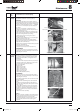
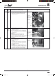
(1) Common
procedure
t%FUBDINFOU
4UPQPQFSBUJPOPGUIFIFBUQVNQBOEUVSOPò
switch of the breaker.
3FNPWFUIFGSPOUQBOFM451tQDT
After unscrewing the screws, remove the front
panel while drawing it downward.
3. Remove the power cable from cord clamp and
terminal.
3FNPWFUIFSPPGQMBUF451tQDT
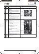
t"UUBDINFOU
.PVOUUIFSPPGQMBUF451tQDT
9. Connect the power cable and to terminal, and then
x them with cord clamp.
REQUIREMENT
Secure the power cables using a tie-wrap or rubber
band to ensure they do not come into contact with
the compressor, valves and discharge pipe.
"UUBDIUIFGSPOUQBOFM451tQDT
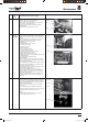
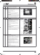
(2) Side
cabinet
t %FUBDINFOU
1. Perform the work from 1 to 4 of (1).
2. Remove the screws xing the inverter assembly and
UIFTJEFDBCJOFU.tQDBOE451t
9.5, 1 pc.).
3. Remove the screws xing the GMC assembly and
UIFTJEFDBCJOFU451tQDT
4. Remove the screw for the side cabinet and the
QJQJOHQBOFM3FBS451tQD
5. Remove the screw for the side cabinet and the base
QMBUF451tQDT
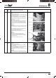
6. Remove the screws for the side cabinet and the n
HVBSE451tQDT
7. Remove the screws of the side cabinet and the
Brazzed plate heat exchanger assembly. (ST8P Ø9.75
tQDT
t "UUBDINFOU
8. Replace the cabinet removed and attach the taken-
PòTDSFXTUPUIFPSJHJOBMQPTJUJPOT
Pump motor
Nuts
Gloves
Gloves
Roof plate
Side cabinet
Front panel
SM_30AW.indd 110 14-03-2011 14:46:44