
Service manual


63
30AW
Control management
5
System Diagnostics
Output test
Pulse Modulating Valve [PMV] control (cooling and heating operation)
The control contains diagnostic tests to verify the integrity of the system.
The On Board LED is located on the circuit board. It is used to display normal operation status and diagnostic fault code
information.
The control board status LED will ash at a rate of one (1) second ON and one (1) second OFF while the control is operating
normally.
When in a diagnostic fault code, it will blink out the fault code.
Once a failure occurs, the system is considered failed. The failure could be recoverable or not. The lowest diagnostic number
that is active will be the fault code that is displayed.
When a diagnostic is active the onboard LED will blink the fault code out. The sequence will be 4 seconds with the onboard
-&%TPò5IFPOCPBSE-&%XJMMCMJOLBUBSBUFPGIBMGTFDPOEPOIBMGTFDPOEPòGPSFBDIOVNCFSJOUIFUFOTEJHJU5IFO
TFDPOETPò5IFPOCPBSE-&%XJMMCMJOLBUBSBUFPGIBMGTFDPOEPOIBMGTFDPOEPòGPSFBDIOVNCFSJOUIFPOFTEJHJU*GUIF
fault code is less than 10 the delay will be 6 seconds between onboard LED ash sequences.
Fault Codes associated with diagnostic will be available through communications.
Fault code 14 and 8 shall be give top priority and shall by pass other fault codes. Fault codes priority order shall be the same
as in the given below table in absence of Fault codes 14 and 8.
SUI Alarm:
When any diagnostic is active and in case SUI is connected, SUI Alarm LED shall blink as just the same way as Onboard LED. In
absence of diagnostics SUI Alarm LED shall remain OFF.
Fault codes on NUI:
Main Board shall communicate the diagnostic with NUI. User or Installer can view these fault codes through an entry into
User settings mode or Installer settings Mode and scroll to the fault code as mentioned in the Variable table. NUI shall scroll all
the active fault codes. In absence of diagnostics, NUI shall display blank. NUI shall also manage to store the latest 4 fault codes
and Installer can view this value by scrolling to Fault code History parameter.
For more information about the fault code on controls NUI and/or SUI refer to their specic manuals.
For specication of fault code refer to the specic paragraph:
i(.$BMBSNDPEFTw
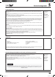
Recoverable:
self healing
diagnostic
Not
Recoverable:
Must cycle
power up to the
unit to x the
system.
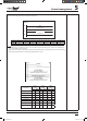
This test will be used by the Installer to test and/or to force ON the outputs, setting the code 104 on the NUI: NUI Code 104
0. No test
1. Water pump
2. Alarm / Ambient temperature reached
3. External Heat Source / Defrost
4. Alarm + defrost / Humidity
5. Trace Heater / Additional Water Pump
6. 3 Way Valve
7. SUI Alarm
8. N.A.
5PQFSGPSNBOZPVUQVUUFTUUIF6OJUNVTUCFJO0òJGOPU0òNVTUCFGPSDFE"GUFSNJOVUFTUIFVOJUBVUPNBUJDBMMZFYJU
GSPNPVUQVUUFTU5PQFSGPSNBOZPVUQVUUFTUUIF6OJUNVTUCFJO0òJGOPU0òNVTUCFGPSDFE
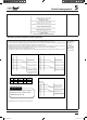
Pulse Modulation Valve is a refrigerant bi-ow electronic expansion device driven by a stepper motor.
It’s use to optimize refrigerant superheating and avoid refrigerant liquid back into the compressor.
1) The PMV is controlled with 50 to 500 pulses during the operation, respectively.
5IF1.7JTDPOUSPMMFEVTJOHUIFUFNQFSBUVSFEJòFSFODFCFUXFFO
54TFOTPSBOE53TFOTPSJODPPMJOHNPEF54TFOTPSBOE5&TFOTPSJOIFBUJOHNPEF5IFUBSHFUJTUPNBJOUBJOUIF
UFNQFSBUVSFEJòFSFODFGSPNUP,
3) During max loading conditions, the refrigerant circuit pressures & temperatures can increase excessively, so the PMV is
controlled by the TD sensor.
TS: Suction
temperature
TR:
Refrigerant
temperature
TE: Entering
(in Heat
exchanger)
temperature
SM_30AW.indd 63 14-03-2011 14:45:10