
Service manual

93
30AW
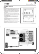
Carrier interfaces
7
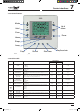
Carrier’s NUI series programmable user interface is wall-mounted,
low-voltage user interface which maintains room temperature by
controlling the operation of a heating and/or air conditioning system.
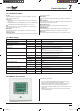
i)FBUQVNQwi"JSDPOEJUJPOFSwBOEi)FBUPOMZwBSFBWBJMBCMFXJUIUIF
present versions. A variety of features are provided including separate
heating and cooling set-points, keypad lockout, backlighting, and built-
in installer test etc. Programming features include 7-day (all days the
same), 5/2 (Mon-Fri and Sat-Sun) and 1-day (all 7 days individually) with
2 or 4 or 6 periods per day.
This Installation Instruction covers installation, conguration, and
startup of NUI. For operational details, consult the Owner’s Manual.
WARNING:
#FGPSFJOTUBMMJOHUIFSFNPUFDPOUSPMMFSUVSOPòBMMQPXFSUPUIFVOJUUIBU
will supply power to the remote controller. Electrical shock can cause
personal injury or death.
User Interface Location
· Approximately 5 ft (1.5m) from oor.
· Close to or in a frequently used room, preferably on an inside
partitioning wall.
· On a section of wall without pipes or duct work.
User Interface should NOT be mounted
· Close to a window, on an outside wall, or next to a door leading to the
outside.
· Exposed to direct light or heat from the sun, a lamp, replace, or other
temperature-radiating objects which could cause a false reading.
· Close to or in direct airow from supply registers and return-air
registers.
· In areas with poor air circulation, such as behind a door or in an alcove.
Install User Interface
Turn OFF all power to unit.1.
If an existing User Interface is being replaced: 2.
a. Remove existing User Interface from wall.
b. Disconnect wires from existing User Interface, one at a time.
c. As each wire is disconnected, record wire colour and terminal
marking.
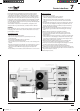
Open the NUI (mounting base) to expose mounting holes. The base 3.
can be removed to simplify mounting. Press the thumb release at
thetop of the NUI and snap apart carefully to separate mounting
base from remainder of the NUI.
Route the NUI wires through large hole in mounting base. Level 4.
mounting base against wall and mark wall through 2 mounting
holes.
Drill two 5mm mounting holes in wall where marked.5.
Secure mounting base to the wall with 2 anchors and screws 6.
provided making sure all the wires extend through hole in the
mounting base.
Adjust length and routing of each wire to reach proper terminal and 7.
connector block on mounting base with 6.5mm of extra wire. Strip
only 6.5mm of insulation from each wire to prevent adjacent wires
from shorting together when connected.
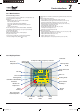
Match and connect equipment wires to proper terminals of the 8.
connector blocks. Refer to wiring diagram for more details.
Push any excess wire into wall and against mounting base. Seal hole 9.
JOXBMMUPQSFWFOUBJSMFBLT-FBLTDBOBòFDUPQFSBUJPO
Snap case back together. Attach thermostat to back plate by 10.
inserting tab on bottom edge and hinging up until top snap secures.
Close thermostat assembly making sure pins on back of circuit board 11.
align with sockets in connector.
Turn ON power to unit.12.
SM_30AW.indd 93 14-03-2011 14:46:02