30HXC 075-370 30GX 080-350 Screw Compressor Water-Cooled Chillers and Air-Cooled Chillers 30HXC Nominal cooling capacity 268-1290 kW 30GX Nominal cooling capacity 262-1160 kW 50 Hz Installation, operation and maintenance instructions
The cover photograph is for illustrative purposes only and is not part of any offer for sale or contract.
List of contents INTRODUCTION ...................................................................... 4 SAFETY CONSIDERATIONS ................................................. 4 DIMENSIONS, CLEARANCES, WEIGHT DISTRIBUTION ...................................................... 5 30HXC 075-185 ........................................................................... 5 30HXC 215-280 ........................................................................... 6 30HXC 300-370 ....................................
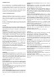
INTRODUCTION Prior to initial start-up of the 30HXC and 30GX unit, those involved in the start-up, operation, and maintenance should be thoroughly familiar with these instructions and other necessary job data. This book provides an overview so that you may become familiar with the control system before performing start-up procedures. Procedures in this manual are arranged in the sequence required for proper machine start-up and operation.
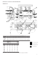
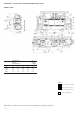
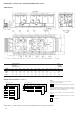
DIMENSIONS, CLEARANCES, WEIGHT DISTRIBUTION 30HXC 075-185 15 ØR 1 14 13 10 34 34 33 33 P1 ØS P3 P2 G H 30HXC A B C D E F L M N ØR 075-095 2730 1775 875 1217 1220 222.5 332 268.3 265.4 2360 1000 593 279 114.3 139.7 105 115-145 2730 3535 1825 1775 875 1035 1217 1635 1220 1220 222.5 332 222.5 332 276.5 300 286 230 2360 3220 1000 1000 593 593 279 734 139.7 139.7 19.7 139.7 160-170 3550 1900 1195 1635 1328 306 257 340 300 3220 1000 620 804 139.
DIMENSIONS, CLEARANCES, WEIGHT DISTRIBUTION (CONT.
DIMENSIONS, CLEARANCES, WEIGHT DISTRIBUTION (CONT.
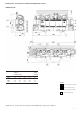
DIMENSIONS, CLEARANCES, WEIGHT DISTRIBUTION (CONT.) 30GX 080-160 30GX A B C D D2 D3 E G H J K R 080-090 2882 2200 627 609.6 409.6 609.6 N/A 515 249 128 2300 114.3 105 115-135 2882 3340 2200 2200 627 856 609.6 609.6 409.6 409.6 609.6 609.6 N/A N/A 558 558 256 256 120 348.5 2300 2100 139.7 139.7 150 4254 2200 627 658.3 1170.5 658.3 2800 497 267 283 N/A 139.7 160 4254 2200 627 658.3 1170.5 658.3 2800 497 267 275 N/A 139.
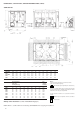
DIMENSIONS, CLEARANCES, WEIGHT DISTRIBUTION (CONT.) 30GX 175 Weight distribution Total at the ten operating mounting holes (kg) weight (kg) 30GX P1 P2 P3 P4 P5 P6 P7 P8 P9 P10 PT 175 506 323 322 635 467 687 527 702 321 181 4671 Multiple chiller installation (see note 2) SOLID SURFACE AREA Notes : 1. Unit must have clearances for air flow as follows : Top : do not restrict in any way SOLID SURFACE AREA 2.
DIMENSIONS, CLEARANCES, WEIGHT DISTRIBUTION (CONT.
DIMENSIONS, CLEARANCES, WEIGHT DISTRIBUTION (CONT.
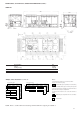
MAIN COMPONENTS LOCATION 30HXC 075-185 2 5 30 27 9 19 26 6 4 28 29 5 9 27 19 26 18 6 4 28 18 30HXC 30HXC 30HXC 30HXC 30HXC 30HXC 30HXC 29 2 115 125 135 145 160 170 185 20 25 21 30HXC 30HXC 30HXC 30HXC 20 25 21 31 32 31 32 3 A 12 11 3 24 23 B 7 22 8 8 24 23 7 22 12 ITEM DESIGNATION ITEM DESIGNATION 1 Cooler water inlet and outlet 18 Capacity loaders 2 3 Cooler 3/8" NPT air vent Cooler 3/8" NPT water drain 19 20 Oil solenoïd valve External muffler 4
MAIN COMPONENTS LOCATION (CONT.
PHYSICAL DATA 30HXC 30HXC 075 085 095 105 115 125 135 145 160 170 185 Nominal gross cooling capacity* kW 268 295 346 373 404 439 485 519 550 593 639 Operating weight** Refrigerant kg 2503 2518 HFC-134a 2560 2731 2833 2872 2956 2971 3283 3403 3517 Refrigerant charge CKT A/CKT B Oil kg See unit nameplate Polyolester oil CARRIER SPEC : PP 47-32 Oil charge CKT A/CKT B Compressor l 20/20 20/20 20/20 Semi-hermetic twin screw 20/20 20/20 20/20 20/20 20/20 20/20 20/2
ELECTRICAL DATA 30HXC 30HXC 075 085 095 105 115 125 135 145 160 170 185 68 80.5 86.4 90.6 98.4 108.7 117.9 124 133 144.3 Mains power supply Nominal voltage V-ph-Hz 400-3-50 Voltage range % ± 10 Control circuit voltage* V-ph-Hz 230-1-50 Nominal unit power input** kW 62.
PHYSICAL DATA 30GX 30GX Nominal gross cooling capacity* Operating weight Refrigerant Refrigerant charge CKT A/CKT B Compressor Ckt A, nominal capacity per compressor Ckt B, nominal capacity per compressor Economizer Capacity steps Minimum capacity Cooler Net water volume Refrigerant circuits Water connection Inlet & outlet diameter Air vent diameter (on water box) Water drain diameter (on water box) Maximum operating pressure water side Condenser fans Number Total air flow Speed 080 kW kg kg Tons Tons No.
ELECTRICAL DATA 30GX 30GX 080 090 105 115 125 135 150 160 175 211,5 Main power supply Nominal voltage V-ph-Hz 400-3-50 Voltage range % ± 10 Control circuit supply* V-ph-Hz 230-1-50 Nominal unit power input** kW 94,2 108,9 124 137,2 151,2 167 178 200,4 Nominal operating current** A 183 200 216 238 256 271 299 325 353 Maximum operating current*** A 230 256 286 322 347 375 424 461 510 Maximum starting current Across the line start**** A 829 970 1087 1358
APPLICATION DATA Maximum chilled water flow Unit operating range The maximum chilled water flow (> 0.09 l/s per kW or < 2.8 K temperature difference) is limited by the maximum permitted pressure drop in the evaporator. It is provided in the following table : a - Select a non-standard evaporator with one water pass less which will allow a higher maximum water flow rate. b - Bypass the evaporator as shown in the diagram to obtain a highter temperature difference with a lower evaporator flow rate.
Cooler flow rate (l/s) Variable flow evaporator 30HXC Min.* Max.** 075-085 095 6.6 6.7 26.2 27.0 105 115-125 9.1 9.3 36.2 37.0 135-145 160-170 11.2 14.1 44.7 56.3 185 215 16.4 17.0 65.5 67.9 250-280 300 21.0 22.2 84.0 88.7 315-370 26.8 107.2 30GX Min.* Max.** 080-090 5.8 21.0 105-115 125-135 6.3 7.4 26.5 31.8 Application N 150 160-175 9.1 10.8 36.0 41.9 Normal air conditioning Process type cooling 3.25 6.5 205 225 12.4 14.5 46.0 54.0 250-265 280-300 16.5 18.0 60.
Flow controllers INSTALLATION Cooler flow switch and chilled water pump interlock Check equipment received IMPORTANT It is mandatory to install cooler flow switch and also to connect chilled water pump interlock on 30HXC and 30GX units using flooded cooler. Failure to this instruction will void Carrier guarantee. • Inspect the unit for damage or missing parts. If damage is detected, or if shipment is incomplete, immediately file a claim with the shipping company.
LIFTING INSTRUCTIONS 30HXC 075-185 This diagram is shown for information only. Refer to “certified drawings” delivered with the unit. 1500 mm min. 1075 mm min. 80° max. CENTER OF GRAVITY 30HXC X (mm) Y (mm) Z (mm) 075-095 1265 376.5 900 105 115-145 1265 1665 376.5 376.5 950 900 160 1855 371.5 950 170-185 1855 380.
LIFTING INSTRUCTIONS (CONT.) 30HXC 215-280 This diagram is shown for information only. Refer to “certified drawings” delivered with the unit. 2800 mm min. 70°C max. 50 mm min. 1050 mm min. CENTER OF GRAVITY NOTE When all lifting and positioning operations are finished, it is recommended to touch up all surfaces where paint has been removed on lifting lugs.
LIFTING INSTRUCTIONS (CONT.) 30HXC 300-370 1000 mm min. 50 mm min. This diagram is shown for information only. Refer to “certified drawings” delivered with the unit. 70° max. CENTER OF GRAVITY NOTE When all lifting and positioning operations are finished, it is recommended to touch up all surfaces where paint has been removed on lifting lugs.
LIFTING INSTRUCTIONS (CONT.) 30GX 080-160 This diagram is shown for information only. Refer to “certified drawings” delivered with the unit.
LIFTING INSTRUCTIONS (CONT.) 30GX 205-265 This diagram is shown for information only. Refer to “certified drawings” delivered with the unit.
PIPING CONNECTIONS Refer to the certified dimensional drawings for the sizes and positions of all water inlet and outlet connections. The water pipes must not transmit any radial or axial force to the heat exchangers or any vibration to the pipework or building. The water supply must be analysed and appropriate filtering, treatment, control devices, isolation and bleed valves and circuits built in, as necessary. Consult either a water treatment specialist or appropriate literature on the subject.
insignifiant particulates) · Presence of corrosives and contaminants, classification 4C2 (negligible) · Vibration, shock : classification 4M2 Competence of personnel : classification BA4(2) (personnel qualified in accordance with IEC 364). ELECTRICAL CHARACTERISTICS • The 30HXC 075-185 and 30GX 080-175 have only one power terminal block. • The 30HXC 215-370 and 30GX 205-350 have two power terminal blocks.
FIELD POWER SUPPLY 30HXC 075-185 15 PE M10 GROUND FIELD CONNECTION Electrical box Power terminal block Main disconnect switch PE M10 GROUND FIELD CONNECTION 16 17 S mm2 S mm2 PE M10 GROUND FIELD CONNECTION S mm2 S mm2 30HXC A (mm) B (mm) B1 (mm) Min. Max. 30HXC A (mm) B (mm) Min. Max. 075-115 125 70 70 40 40 25 25 70 95 120 120 075-115 125 125 125 236 236 70 95 120 120 135-185 70 62.
FIELD POWER SUPPLY (CONT.) 30HXC 215-280 PE M10 GROUND FIELD CONNECTION CONNECTION Electrical box CKT B Power terminal block 15 CKT A Main disconnect switch PE PE M10 M10 GROUND GROUND FIELD FIELD CONNECTION CONNECTION 16 SA mm2 17 SB mm2 PE PEM10 M10 GROUND GROUNDFIELD FIELD CONNECTION CONNECTION SA mm2 SB mm2 30HXC A (mm) Min. Max. Min. Max. 30HXC A (mm) Min. Max. Min. Max.
FIELD POWER SUPPLY (CONT.) PE PEM10 M10 GROUND FIELD CONNECTION GROUND FIELD CONNECTION 30HXC 300-370 Electrical box CKT B Power terminal block CKT A Main disconnect switch PE M10 GROUND FIELD CONNECTION PE PE M10 M10 GROUND GROUND FIELD FIELD CONNECTION CONNECTION SA mm2 SA mm2 2 SB mm2 SB mm 30HXC A (mm) B (mm) C (mm) Min. Max. 30HXC A (mm) B (mm) Min. Max. 300 70 40 85 95 120 300 125 236 95 120 315-370 70 62.
FIELD POWER SUPPLY (CONT.) 30GX 080-160 Electrical box PE M12 PE M10 GROUND FIELD GROUND FIELD CONNECTION CONNECTION Ø 12 Power terminal block Main disconnect switch S mm2 S mm2 30GX B (mm) Min. Max. 30GX A (mm) B (mm) Min. Max.
FIELD POWER SUPPLY (CONT.) 30GX 175 Electrical box PEM10 M12 PE GROUNDFIELD FIELD GROUND CONNECTION CONNECTION Ø 12 Power terminal block Main disconnect switch S mm2 S mm2 30GX Min. Max. 30GX Min. Max. 175 2x120 2x300 175 2x120 2x185 IMPORTANT Before the connection of the main power cables (L1 - L2 - L3) on the power terminal block, it is imperative to check the right order of the 3 phases before proceeding to the connection on the terminal block or the main disconnect switch.
FIELD POWER SUPPLY (CONT.) 30GX 205-265 Electrical box PE M12 PE M12 FIELD GROUND GROUND FIELD CONNECTION CONNECTION Power terminal block Main disconnect switch SA mm2 SB mm2 SA mm2 SB mm2 30GX Min. Max. Min. Max. 30GX Min. Max. Min. Max.
FIELD POWER SUPPLY (CONT.) 30GX 280-350 Electrical box PE M12 GROUND FIELD CONNECTION Power terminal block Main disconnect switch SA mm2 SB mm2 SA mm2 SB mm2 30HXC Min. Max. Min. Max. 30HXC Min. Max. Min. Max.
MAJOR SYSTEM COMPONENTS AND OPERATION DATA which separates the two refrigerant circuits. The tubes are 3/4" or 1" diameter copper with enhanced surface inside and out. There is just one water circuit with two water passes. Geared twin screw compressor • 30HXC and 30GX units use 06N geared twin screw compressors • 06NA are used on 30GX (air-cooled condensing application) • 06NW are used on 30HXC (water-cooled condensing application) • Nominal capacities range from 39 to 80 tons.
the EXV flashes to vapor, further subcooling the liquid that is maintained at the bottom of the economizer. This increase in subcooling provides additional capacity. Since no additional power is required to accomplish this, the efficiency of the machine also improves. The vapor that flashes will rise to the economizer where it passes to the compressor and is used as needed to provide motor cooling.
Compressor Protection Module (CPM) This module monitors several of the compressor safeties and controls four of the outputs used to control the compressor. The CPM monitors compressor current, compressor voltage, high pressure switch status, and compressor motor temperature. It controls the compressor contactor oil solenoid, motor cooling solenoid, and star delta transition relay. Each CPM sends the PSIO its circuit motor temperature, alarm status and the output status of the module.
The CPM communicates on the COMM3 communication bus to the PSIO module. Proper operation of the CPM board can be verified by observing the three LED's located on the board. The left LED is red and blinks to indicate that the module is powered and operating correctly. The middle LED is yellow and blinks when there is an automatic reset alarm condition. The yellow LED will remain on and will not blink for manual reset alarm conditions.
CONTROL OPERATION Keypad and display module usage (HSIO II) FUNCTION USE OPERATIVE KEYS USE KEYS STATUS - For displaying diagnostic codes and current operating information about the machine. EXPAND - For displaying a non-abbreviated expansion of the display. HISTORY - For displaying run time, cycles and previous alarms. CLEAR - For clearing the screen of all displays. <↑> UP ARROW - For returning to previous display position.
Accessing functions and subfunctions OPERATION KEYPAD ENTRY DISPLAY RESPONSE To access a function, press subfunction no. and function name key. Display shows subfunction group <1> Circuit A Discrete Outputs To move to other elements, scroll up or down using arrow keys. <↓> Loader A2 Relay is OFF <↓> Hot Gas Bypass Valve A Relay is OFF Circuit A Oil Heater Relay is OFF A1 Mtr. Cooling Solenoid Relay is OFF A2 Mtr.
Status function This function shows the rotating display, current status of alarm and alert (diagnostic) codes, capacity stages, operating modes, chilled water setpoint, all measure system temperatures and pressures, analog inputs, and switch inputs. Alarms/Alerts Alarms and alerts are messages that indicate that one or more faults have been detected. See Table for definitions.
STATUS (CONT.) STATUS (CONT.) SUBFUNCTION KEYPAD ENTRY DISPLAY COMMENT 4 Circuit A discrete <4> CIR. A DISCRETE OUTPUTS Outputs SUBFUNCTION KEYPAD ENTRY 7 Unit Analogue <7> UNIT ANALOGUE PARAMETERS Parameters <↓> Cooler Entering Fluid COMMENT Displays xx.x °C Displays xx.x °C <↓> Compressor A1 Displays Off/On <↓> Cooler Leaving Fluid <↓> Compressor A2 Displays Off/On <↓> Condenser Entering Fluid Displays xx.
STATUS (CONT.) SUBFUNCTION 10 Capacity Control TEST (CONT.) KEYPAD ENTRY DISPLAY <↓> <↓> <↓> <↓> COMMENT SUBFUNCTION KEYPAD ENTRY 2 CHLLR COMM FAILURE 3 Unit Discrete <3> UNIT DISCRETE OUTPUT. CIR A LOW DISCHG SUPERHT Output <↓> Fan 1 CIR B LOW DISCHG SUPERHT <↓> Fan 2 CIR A HIGH SDT <↓> Fan 3 <↓> CIR B HIGH SDT <↓> Fan 4 <10> CAPACITY CONTROL <↓> Fan 5 <↓> Load/Unload Factor Displays xxx.x % <↓> Fan 6 <↓> Control Point Displays xx.
TEST (CONT.) SUBFUNCTION KEYPAD ENTRY DISPLAY COMMENT 4 Valves and <4> VALVES AND MOTOR MASTER Motor Master <↓> Circuit A EXV Valve Target Percent = 0 % <1> <1> Step in 25% increments. EXV may be moved to a specific percent by entering the desired value and pressing . Wait 30 seconds between each step for valve to stop moving. SUBFUNCTION KEYPAD ENTRY DISPLAY 1 Service <1> SOFTWARE CESR 500100 <↓> Unit Type Configuration Ver.
SERVICE (CONT.) SUBFUNCTION SERVICE (CONT.) KEYPAD ENTRY DISPLAY COMMENT SUBFUNCTION KEYPAD ENTRY DISPLAY <↓> Water Valve Type 0 = None (Default), 1 = 4-20 mA, 2 = 0-10 V, 3 = 20-4 mA, 4 = 10-0 V 4 Reset <4> COOLING RESET TYPE 1 Configuration table <↓> Degrees reset at 20 mA xx.x dC <↓> <↓> <↓> <↓> <↓> COOLING RESET TYPE 2 Ext. Reset Sensor Select 0 = Space Temp. Thermistor (Default) <↓> Remote temp = no reset xx.
SERVICE (CONT.) SERVICE (CONT.
Setpoint function SETPOINT (CONT.) SUBFUNCTION KEYPAD ENTRY DISPLAY <↓> Minutes off time xxx min. <↓> Motor Temp. setpoint xxx.x °C 2 Units <2> US IMPERIAL/METRIC 0 3 Address <3> TARGET ADDRESS x <↓> TARGET BUS NUMBER x <4> Day of week Monday Mon = 1, Tues = 2 etc. <3> Day of week Wednesday Day of week set <↓> TIME (HOUR:MIN) 00:00 Enter military format <10.
Head pressure control General The microprocessor controls the condenser fans (30GX) or analogue water valve (30HXC) to maintain the saturated condensing temperature to a configurable setpoint. The fans will be staged (30GX) or water valve controlled (30HXC) based on each circuit's saturated condensing temperature and compressor status. Water-cooled units (30HXC) operating at less than 20°C for entering condenser water require the use of head pressure control.
30GX fan arrangement 30GX 080-090-105 30GX 250-265 30GX 115-125-135 30GX 280 30GX 150-160 30GX 295 30GX 175-205-225 30GX 325-350 Fan stage Fans controlled on the unit on HSIO FAN 1 FAN 2 FAN 3 FAN 4 FAN 5 FAN 6 080-105 115-135 EV 12 EV 13,14 EV 13,14 EV 15,16 - - EV 11 EV 11,12 - 150-160 175-225 EV 13,14 EV 13,14 EV 15 to 18 EV 15,16 EV 33,34 - EV 11,12 EV 11,12 EV 31,31 250-265 280 EV 13,14 EV 13,14 EV 15,16 EV 15,16 EV 33,34 EV 33,34 EV 35,36 EV 11,12 EV 11,12 EV 31,32
PRE-START-UP PROCEDURE START-UP AND OPERATION Do not attempt to start the chiller until the following checks have been completed. Actual Start-up System Check 1 - Check all auxiliary components such as the chilled fluid circulating pump, air-handling equipment, or other equipment to which the chiller supplies liquid. Consult the manufacturer’s instructions. If the unit has field-installed accessories, be sure all are properly installed and wired correctly. Refer to the unit wiring diagrams.
TROUBLESHOOTING Single Circuit Stoppage The 30HXC/GX Screw chiller control has many features to aid the technicians in troubleshooting. By using the keypad and display module and the status function, actual operating conditions of the chiller are displayed while the unit is running. The test function allows for operational checkout of compressor loaders, EXV’s, solenoids and other components while the chiller is stopped.
Alarms and alerts codes table Alarm/Alert code Alarm or Alert Description Why was this alarm generated ? Action taken by control Reset method Probable cause – 0 – No alarms or alerts exist – – 1.xx Alert Compressor A1 failure See CPM subcodes below See CPM subcodes below Manual 2.xx Compressor A2 failure See CPM subcodes below See CPM subcodes below Manual 5.xx Compressor B1 failure See CPM subcodes below See CPM subcodes below Manual 6.
Alarms and alerts codes table (cont.) Alarm/Alert code Alarm or Alert Description Why was this alarm generated ? Action taken by control Reset method Probable cause 11 Alert Condenser leaving fluid Thermistor failure Thermistor outside range of of -40 to 118°C None. Chiller continues to run Automatic Thermistor failure, damaged cable/wire or wiring error. 12 Alert Condenser entering fluid Thermistor failure Thermistor outside range of of -40 to 118°C None.
Alarms and alerts codes table (cont.) Alarm/Alert code Alarm or Alert Description Why was this alarm generated ? Action taken by control Reset method Probable cause 40 Alert Compressor A1 low oil pressure Oil pressure differential below oil Setpoint 1 or 2 (see low oil pressure Alert Criteria and Setpoints) Comp.
Alarms and alerts codes table (cont.) Alarm/Alert code Alarm or Alert Description Why was this alarm generated ? Action taken by control Reset method Probable cause 67 Alert Circuit A high discharge pressure SCT > MCT_SP + 2.8°C Circuit A shut down Automatic Faulty transducer/high pressure switch, restricted condenser water flow. 68 Alert Circuit B high discharge pressure SCT > MCT_SP + 2.
Low oil pressure alert criteria and setpoints (Alert 40 to 43) Two oil pressure setpoints are used. Oil setpoint 1 and oil setpoint 2. Oil setpoint 1 (oil pressure differential Po - Pe) is calculated as follows: 30HXC Oil setpoint 1 = 70 kPa if saturated suction pressure ≤ 240 kPa Oil setpoint 1 = 86 kPa if saturated suction pressure > 240 kPa but < 450 kPa Oil setpoint 1 = 100 kPa if saturated suction pressure > 450 kPa.
MAINTENANCE To add charge to the 30HXC systems Refrigerant Charging - Adding Charge 1. Make sure that the unit is running at full-load, and that the cooler leaving fluid temperature is in the range of 5.6 - 7.8 °C. IMPORTANT These units are designed for use with R-134a only. DO NOT USE ANY OTHER refrigerant in these units. CAUTION When adding or removing charge, circulate water through the condenser (HX) and cooler at all times to prevent freezing.
5. Add 2.5 kg of liquid charge into the cooler using charging valve located in the top of the cooler. 6. Allow the system to stabilize and then recheck the liquid temperature. Repeat step 5 as needed allowing the system to stabilize between each charge addition. Slowly add charge as the sightglass begins to clear to avoid overcharging. Oll Charging - Low oil recharging Addition of oil charge to 30HX/GX systems 1.
Service replacement compressor EXV Troubleshooting Procedure Compressor rotation control Follow steps below to diagnose and correct EXV/ Economizer problems. Correct compressor rotation is one of the most critical application considerations. Reverse rotation, even for a very short duration, can seriously affect the reliability of the compressor. The reverse rotation protection scheme must be capable of determining the direction of rotation and stopping the compressor within 300 milliseconds.
START-UP CKECKLIST FOR 30HXC/GX LIQUID CHILLERS (USE FOR JOB FILE) Preliminary information Job name: ................................................................................................................................................................................................ Location: .................................................................................................................................................................................................
Check condenser system (30HXC) All condenser water valves are open All condenser piping is connected properly All air has been vented from the system Condenser water pump (CWP) is operating with the correct rotation. Condenser water pump amperage: Rated: ................... Actual ........................
Check pressure drop across the condenser (30HXC only) Entering condenser = ................................ (kPa) Leaving condenser = ................................. (kPa) (Leaving - entering) = ............................... (kPa) WARNING Plot condenser pressure drop on performance data chart (in product data literature) to determine total liters per second (l/s) and find unit's minimum flow rate. Total l/s = .................................................. l/s / nominal kW = .........................
Review and record field configuration, <2> External reset sensor ................................................................... Cooler pump interlock ................................................................ Cooler pump control ................................................................... Condenser pump control* ........................................................... Condenser flow switch* .............................................................. Condenser water sensors* ..
BP 49 Route de Thil 01122 MONTLUEL - FRANCE Tel: 04 72 25 21 21 Telex: 900386 Fax: 04 72 25 22 51 Order No: 13173-76, March 1997 - Supersedes No: 13173-76, November 1996 Printed in the Netherlands on chlorine-free paper. Manufacturer reserves the right to change any product specifications without notice. Manufacturer: Carrier s.a., Montluel, France.