
Specifications

26
1
5
3
7
2
6
10
4
8
12 9
11
PIPING CONNECTIONS
Refer to the certified dimensional drawings for the sizes and
positions of all water inlet and outlet connections. The water pipes
must not transmit any radial or axial force to the heat exchangers
or any vibration to the pipework or building.
The water supply must be analysed and appropriate filtering,
treatment, control devices, isolation and bleed valves and circuits
built in, as necessary. Consult either a water treatment specialist
or appropriate literature on the subject.
Operating precautions
The water circuit should be designed to have the least number of
elbows and horizontal pipe runs at different levels. The following
basic checks should be done (see also the illustration of a typical
hydraulic circuit below).
• Note the water inlets and outlets of the heat exchangers.
• Install manual or automatic air purge valves at all high points
in the water circuit.
• Use an expansion chamber or an expansion/relief valve to
maintain pressure in the system.
• Install water thermometers in both the entering and leaving
water connections close to the evaporator.
• Install drain valves at all low points to allow the whole circuit
to be drained. Connect a stop valve in the drain line before
operating the chiller.
• Install stop valves, close to the evaporator, in the entering and
leaving water lines.
• Install cooler flow switch.
• Use flexible connections to reduce the transmission of vibration
to the pipework.
• Insulate all pipework, after testing for leaks, both to reduce
thermal leaks and to prevent condensation.
• Cover the insulation with a vapour barrier.
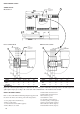
Cooler and condenser connections
The cooler and condenser are of the multi-tube shell and tube
type with removable water boxes to facilitate cleaning of the tubes.
Before making water connections tighten the bolts in both heads to
the lower torque shown, following the method described. Tighten
in the pairs and sequence indicated according to the size of bolt (see
table) using a torque value at the low end of the range given.
CAUTION
Remove the factory supplied flat flange from the water box
before welding piping to the flange. Failure to remove the flange
may damage the sensors and insulation.
Pipe connections
After welding the pipes to the flanges previously removed from
the water boxes :
a - Reinstall the pipes and tighten lightly to a torque at the low
end of the range.
b - Fill the system with water.
c - Wait for 10 minutes and check for minor leaks
- at the water box joints
- at the flange joints
d - Drain the system.
e - Disconnect the pipework.
f - Tighten the head bolts to their final torque (middle of the
range) in the sequence illustrated.
g - Reconnect the pipes, tightening the flange bolts to the mid-
range torque value.
h - Refill the system with water.
i - Pressurize the system.
NOTE
We recommend draining the system and disconnecting the
pipework to ensure that the bolts of the heads to which the
pipework is connected are correctly and uniformly tightened.
If there is a leak outside the water head :
a - Drain the system.
b - Disconnect the water pipes.
c - In the correct sequence, retighten the head bolts to the
maximum torque given for the bolt size.
d - Reconnect the pipework, tightening the bolts to their final torque
value, i.e. the middle value in the range given for the bolt size.
e - Refill the system with water.
f - Pressurize the system.
IMPORTANT
Before starting the unit, be sure all of the air has been purged
from the system.
Freeze protection
Cooler and water-cooled condenser protection
If the chiller or the water piping is in an area where the ambient
temperature can fall below 0°C it is recommended to add an
antifreeze solution to protect the unit and the water piping to a
temperature of 8 K below the lowest anticipated temperature.
Use only antifreeze solutions, approved for heat exchanger duty.
If the system is not protected by an antifreeze solution and will
not be used during the freezing weather conditions, draining of
the cooler and outdoor piping is mandatory.
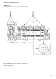
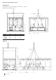
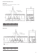
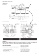
Water box tightening sequence
TIGHTENING TORQUE
BOLT SIZE M16 - 171 - 210 Nm
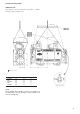
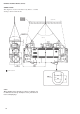
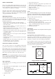
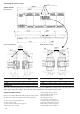
Typical hydraulic circuit diagram
CONTROL
VALVE
AIR
VENT
FLOW SWITCH
HEAT
EXCHANGER
DRAIN
BUFFER
TANK
FILTER
EXPANSION TANK
FILL VALVE
FLEXIBLE CONNECTION
PRESSURE TAP
THERMOSTAT SLEEVE
SEQUENCE 1 : 1 2 3 4
SEQUENCE 2 : 5 6 7 8
SEQUENCE 3 : 9 10 11 12