
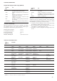
Specifications
35
MAJOR SYSTEM COMPONENTS
AND OPERATION DATA
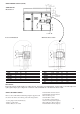
Geared twin screw compressor
• 30HXC and 30GX units use 06N geared twin screw
compressors
• 06NA are used on 30GX (air-cooled condensing application)
• 06NW are used on 30HXC (water-cooled condensing application)
• Nominal capacities range from 39 to 80 tons. Economized or non
economized models are used depending on the 30HXC and 30GX
unit size.
Oil Filter
The 06N screw compressor has an oil filter integral in the compressor
housing. This filter is field replaceable.
Refrigerant
The 06N screw compressor is specially designed to be used in R134
a system only.
Lubricant
The 06N screw compressor is approved for use with the following
lubrifiant.
CARRIER MATERIAL SPEC PP 47-32
Oil Supply Solenoid Valve
An oil supply solenoid valve is standard on the compressor to isolate
the compressor from oil flow when the compressor is not operating.
The oil solenoid is field replaceable.
Suction & Economizer Screens
To increase the reliability of the compressor, a screen has been
incorporated as a standard feature into suction and economizer inlets
of the compressor.
Unloading System
The 06N screw compressor has an unloading system that is standard
on all compressors. This unloading system consists of two steps of
unloading that decrease the compressor capacity by rerouting
partially compressed gas back to suction.
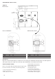
Cooler
30HXC and 30GX chillers use a flooded cooler. Flooded style
coolers have refrigerant in the shell and water in the tubes. One
vessel is used to serve both refrigerant circuits. There is a center
tube sheet which separates the two refrigerant circuits. The tubes
are 3/4" diameter copper with an enhanced surface inside and out.
There is just one water circuit, and depending on the size of the
chiller, there may be two or three water passes. A cooler liquid level
sensor provides optimized flow control.
At the top of the cooler are the two suction pipes, one in each
circuit. Each has a flange welded to it, and the compressor mounts
on the flange.
Condenser and oil separator (30HXC)
30HXC chiller use a vessel that is a combination condenser and oil
separator. It is mounted below the cooler. Discharge gas leaves the
compressor and flows through an external mufler to the oil separator,
which is the upper portion of the vessel. It enters the top of the
separator where oil is removed, and then flows to the bottom portion
of the vessel, where gas is condensed and subcooled. One vessel is
used to serve both refrigerant circuits. There is a center tube sheet
which separates the two refrigerant circuits. The tubes are 3/4" or
1" diameter copper with enhanced surface inside and out. There is
just one water circuit with two water passes.
Oil separator (30GX)
In the air-cooled units, the oil separator is a pressure vessel that is
mounted under the outside vertical condenser coils. Discharge gas
enters at the top of the separator where much of the oil separates
and drains to the bottom. The gas then flows through a wire mesh
screen where the remaining oil is separated and drains to the bottom.
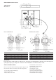
Electronic Expansion Device (EXD)
The microprocessor controls the EXD through the EXV control
module. The EXD will either be an EXV or an Economizer. Inside
both these devices is a linear actuator stepper motor.
High-pressure liquid refrigerant enters the valve through the bottom.
A series of calibrated slots are located inside the orifice assembly.
As refrigerant passes through the orifice, the pressure drops and the
refrigerant changes to a 2-phase condition (liquid and vapor). To
control refrigerant flow for different operating conditions, the sleeve
moves up and down over the orifice, thereby changing orifice size.
The sleeve is moved by a linear stepper motor. The stepper motor
moves in increments and is controlled directly by the processor
module. As the stepper motor rotates, motion is transferred into
linear movement by the lead screw. Through the stepper motor and
lead screws, 1500 discrete steps of motion are obtained. The large
number of steps and long stroke result in very accurate control of
refrigerant flow. Each circuit has a liquid level sensor mounted
vertically into the top of the cooler shell. The level sensor consists
of a small electric resistance heater and three thermistors wired in
series positioned at different heights inside the body of the well.
The heater is designed so that the thermistors will read approximately
93.3°C in dry air. As the refrigerant level rises in the cooler, the
resistance of the closest thermistor(s) will greatly change. This large
resistance difference allows the control to accurately maintain a
specified level. The level sensor monitors the refrigerant liquid level
in the cooler and sends this information to the PSIO-1. At initial
start-up, the EXV position is at zero. After that, the microprocessor
keeps accurate track of the valve position in order to use this
information as input for the other control functions. It does this by
initializing the EXV’s at startup. The processor sends out enough
closing pulses to the valve to move it from fully open to fully closed,
then resets the position counter to zero. From this point on, until the
initialization, the processor counts the total number of open and
closed steps it has sent to each valve.
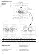
Economizer
Economizers are installed on 30HXC 170 to 370 (except 30HXC
215) and 30GX 105 to 350.
The economizer improves both the chiller capacity and efficiency
as well as providing compressor motor cooling. Inside the
economizer are both a linear EXV stepper motor and a float valve.
The EXV is controlled by the PIC to maintain the desired liquid
level in the cooler (as is done for Non-Economized chillers). The
float valve maintains a liquid level in the bottom of the economizer.
Liquid refrigerant is supplied from the condenser to the bottom of
the economizer. As the refrigerant passes through the EXV, its
pressure is reduced to an intermediate level of about 500 kPa. This
pressure is maintained inside the economizer shell. Next, the
refrigerant flows through the float valve, its pressure is further
reduced to slightly above the pressure in the cooler. The increase in
performance is realized when some of the refrigerant passing through