
Specifications

37
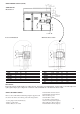
Control components
Processor module (PSIO)
It contains the operating software and controls the operation of the
machine. It has 12 input channels and 6 output channels.
It continuously monitors input/output channel information received
from all the modules and controls all output signals for all output
channels. It also controls relays. The processor module also controls
the EXV control module, commanding it to open or close each
EXD in order to maintain the proper cooler level. Information is
transmitted between the processor module, CPM modules, the EXV
control module, the basic board and HSIO II display module through
a 3-wire communications bus called COMM3.
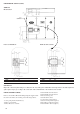
Basic board
It is used as input/output module as there is no unit software
downloaded in this module. It contains 8 analogue inputs, 14 discrete
inputs and 8 discrete outputs.
Electronic expansion valve module
This module has four outputs. It receives signals from the PSIO
module and operates the electronic espansion device.
Optional control module
An optional control module with 4 analogue inputs and 2 discrete
outputs is added for remote control. Demand limit control (4-20
mA) and chilled water temperature reset (4-20 mA).
Control switch
Control of the chiller is defined by the position of the LOCAL/
OFF/REMOTE (LOR) switch. This is a 3-position manual switch
that allows the chiller to be put under the control of its own controls,
manually stopped or controlled through a set of remote contacts.
CCN control is done through the HSIO II. In the LOCAL position,
the chiller is allowed to operate and respond to the scheduling
configuration, CCN configuration and set point data. In the remote
position the unit operates similar to the LOCAL position except the
remote contact must be closed for the unit to be able to operate.
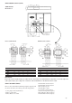
Compressor Protection Module (CPM)
This module monitors several of the compressor safeties and controls
four of the outputs used to control the compressor. The CPM
monitors compressor current, compressor voltage, high pressure
switch status, and compressor motor temperature. It controls the
compressor contactor oil solenoid, motor cooling solenoid, and star
delta transition relay. Each CPM sends the PSIO its circuit motor
temperature, alarm status and the output status of the module.
The CPM provides the following functions:
• Compressor main contactor control
• Star delta contactor transition
• Compressor ground current protection
• Reads motor temperature
• High-pressure protection
• Reverse rotation protection
• Voltage imbalance protection
• Current imbalance protection
• Compressor oil solenoid control
• Motor cooling solenoid control
• Sensor bus communications
• Starting and running overcurrent protection
The CPM has four output relays and four inputs.
OUTPUTS:
• Compressor contactor
• Compressor oil solenoid
• Compressor motor cooling solenoid
• Star delta transition relay
INPUTS:
• Motor temperature
• 3-phase voltage
• 3-phase current
• High pressure switch
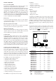
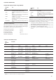
A diagram of the CPM board is shown below. There are line
voltage inputs at L1, L2 and L3. Next to these inputs are the
current torroid inputs at plug 1. Next to plug 1 are the three
COMM3 communication terminals. In the lower right corner of
the board are the inputs for motor winding temperature. The
address dip switch and compressor Must Trip Amps header are
factory set.
On the board, at the top left is a 9-pin plug 2, where power is
supplied to the board and where the outputs loads are connected.
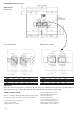
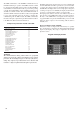
To verify proper Must Trip Amps header configuration, press <1>
<SRVC> and use the key on the HSIO II.
Compressor Protection Module (CPM)
T
T
1
2
3
L1
L2
L3
ADDRESS DIP SWITCH
COMPRESSOR MUST
TRIP AMPS HEADER
CURRENT TOROID
INPUT PLUG 1
24 VAC
INPUTS/
OUTPUTS
PLUG 2
LINE VOLTAGE INPUTS COMMUNICATION BUS
COMM3
MOTOR
TEMPERATURE INPUT
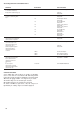
COMPRESSOR Tons MTA Compressor MTA
PART NUMBER Header Configuration
06NW 1146 S7 N 39 81 00010000
06NW 1174 S7 N 46 99 00011000
06NW 1209 S7 N 56 119 00100011
06NW 1250 S7 N 66 143 00101110
06NW 1300 S5 N 80 174 00111110
06NW 1209 S7 E 56 130 00101000
06NW 1250 S7 E 66 156 00110101
06NW 1300 S5 E 80 189 01000110
06NA 1146 S7 N 39 119 00100011
06NA 1174 S7 N 46 145 00110000
06NA 1209 S7 N 56 175 00111111
06NA 1146 S7 E 39 134 00101010
06NA 1174 S7 E 46 163 00111000
06NA 1209 S7 E 56 195 01001000
06NA 1250 S7 E 66 236 01011101
06NA 1300 S5 E 80 293 01111010
Legend:
MTA Compressor Must Trip Amps
N Non Economized compressor
E Economized compressor
06NW Water-cooled condensing compressor
06NA Air-cooled condensing compressor
Header configuration:
0 broken jumper from left to right
1 existing jumper from left to right