
Specifications

38
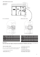
The CPM communicates on the COMM3 communication bus to
the PSIO module. Proper operation of the CPM board can be verified
by observing the three LED's located on the board. The left LED is
red and blinks to indicate that the module is powered and operating
correctly. The middle LED is yellow and blinks when there is an
automatic reset alarm condition. The yellow LED will remain on
and will not blink for manual reset alarm conditions. The right LED
is green and will blink when the module is satisfactorily
communicating with the PSIO module. The CPM communicates
the status of its inputs, outputs and reports different alarm conditions
to the PSIO. The alarms are listed in table below:
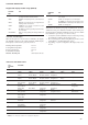
Compressor protection module code table
Condition Value
High pressure switch trip 1.0
No motor current 2.0
Current imbalance warning 10 % 2.5
Current imbalance alarm 10 % 2.7
Current imbalance 18 % 3.0
Single phase current loss 3.5
High motor current 4.0
Ground fault 5.0
Voltage imbalance warning 3 % 5.5
Voltage imbalance alarm 3 % 5.7
Voltage imbalance 7 % 6.0
Single phase voltage loss 6.5
Voltage phase reversal 7.0
Contactor failure 7.5
Current phase reversal 8.0
Motor over temperature 8.5
Open thermistor 9.0
Configuration header fault 9.5
Shorted thermistor 10.0
No Error 0
WARNING
The CPM module has many features that were specifically
designed to protect the compressor including reverse rotation
protection. Do not attempt to bypass or alter any of the factory
wiring. Any compressor operation in the reverse direction will
result in a compressor failure that will require replacement.
The PSIO will generate an alert when it receives an alarm input
from the CPM. The alert will be generated in a y.xx format where
"y" refers to the compressor and "xx" to the alarm value. For example,
the HSIO II would display Alert 1.65 for a single phase voltage loss
occurring on compressor A1. Similarly, the display would read 5.85
for a motor over-temperature condition on compressor B1.
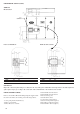
The high-pressure switch is wired in series with the relay coils of
the four relays on the CPM. If this switch opens during operation,
all relays on the CPM will be de-energized and the compressor
stopped. The failure is reported to the PSIO and the processor module
will lock off the compressor from restarting until the alarm is
manually reset.
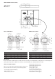
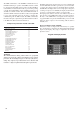
Keypad and Display Module (HSIO II)
This device consists of a keypad with 8 function keys, 4 operative
keys, 12 numeric keys, and a 2 line-24 character alphanumeric LCD
(liquid crystal display). Key usage is explained in the Control
Operation section.
Keypad and display module