
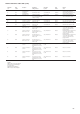
Specifications


51
TROUBLESHOOTING
The 30HXC/GX Screw chiller control has many features to aid
the technicians in troubleshooting. By using the keypad and
display module and the status function, actual operating conditions
of the chiller are displayed while the unit is running. The test
function allows for operational checkout of compressor loaders,
EXV’s, solenoids and other components while the chiller is
stopped. The Service function displays how configurable items
are configured and provides a manual control mode where the
compressors can be started and loaded. If an operating fault is
detected, an alarm is generated and an alarm code is displayed
under the subfunction <1> <STAT> along with an explanation of
the fault. Up to 10 current alarm codes are stored under this
subfunction.
Checking display codes
To determine how the machine has been programmed to operate,
check the diagnostic information displayed in the Status function
and the configuration displayed in the Service function.
Unit shutoff
To shut the unit off, move the LOCAL/OFF/REMOTE switch to
OFF position. All compressors and solenoids stop immediately.
Complete unit stoppage
Complete unit stoppage can be caused by any of the following
conditions:
1 - Cooling load satisfied.
2 - Remote on/off contacts open.
3 - Programmed schedule.
4 - Emergency stop command from CCN.
5 - General power failure.
6 - Blown fuse in control power feed disconnect.
7 - Open control circuit fuse(s)
8 - LOCAL/OFF/REMOTE switch moved to OFF position.
9 - Freeze protection trip.
10 -Low flow protection trip.
11 -Open contacts in chilled water flow switch.
12 -Open contacts in any auxiliary interlock. Terminals that are
jumpered from factory are in series with control switch.
Opening the circuit between these terminals places unit in
stop mode, similar to moving the control switch to OFF
position. Unit cannot start if these contacts are open. If they
are open while unit is running, the unit stops.
13 -Cooler entering or leaving fluid thermistor failure.
14 -Low/high transducer supply voltage.
15 -Loss of communications between processor module and
other control modules.
16 -Low refrigerant pressure.
17 -Off-to-on delay is in effect.
Single Circuit Stoppage
Single circuit stoppage can be caused by the following:
18 -Low oil pressure.
19 -Open contacts in high pressure switch (1330 kPa on 30HXC
and 2180 kPa on 30GX)
20 -Low refrigerant pressure.
21 -Thermistor failure.
22 -Transducer failure.
23 -Alarm condition from CPM module.
24 -Overload relay trip. Stoppage of one circuit by a safety device
action does not affect other circuit. When a safety device trips,
the circuit is shut down immediately and EXV closes.
Restart procedure
After the cause for stoppage has been corrected, restart is either
automatic or manual, depending on the fault. Manual reset requires
that the alarm(s) be reset via the HSIO II. Press <1> <STAT> and
then <1> <ENTR> to clear manual reset alarms. If the Alarm
Reset Select feature is selected (<3> <SRVC>), a manual reset
alarm can also be reset by switching the LOR switch from
LOCAL/REMOTE to OFF and back to LOCAL/REMOTE again.
If an alarm was from the CPM module, manual reset requires
that the alarm(s) be reset via the control circuit breaker QF2. Some
typical fault conditions are described below. For a complete list
of fault conditions, codes, and reset type, see the Alarm and Alert
codes table.
Power failure external to the unit - Unit restarts automatically
when power is restored.
Alarms and alert
These are warnings of abnormal or fault conditions, and may cause
either one circuit or the whole unit to shut down. They are assigned
code numbers as described below. The alarm descriptions are
displayed on the HSIO II when the <1> <STAT> subfunction is
entered.
Following is a detailed description of each alarm and alert code
error and possible cause. Manual reset is accomplished by entering
<1> <STAT> from the HSIO II and pressing <1> <ENTR> or
moving the LOCAL/OFF/REMOTE switch to the OFF position,
then back to LOCAL or REMOTE position (if Alarm Reset Select
is enabled). See Table below for listing of each alarm and alert
code.