
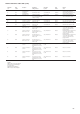
Specifications


58
5. Add 2.5 kg of liquid charge into the cooler using charging
valve located in the top of the cooler.
6. Allow the system to stabilize and then recheck the liquid
temperature. Repeat step 5 as needed allowing the system to
stabilize between each charge addition. Slowly add charge as
the sightglass begins to clear to avoid overcharging.
Oll Charging - Low oil recharging
Addition of oil charge to 30HX/GX systems
1. If the 30HXC/GX unit shuts-off repeatedly on Low oil Level
(alarm number 71 or 72), this may be an indication of
inadequate oil charge. It could also mean simply that oil is in
the process of being reclaimed from the low-side of the system.
2. Begin by running the unit at full-load for an hour and a half.
It is recommended to use the Manual Control feature of the
software if the unit does not normally run at full load.
3. After running for 1-1/2 hours allow the unit to re-start and
run normally. If the Low Oil Level alarms persist, continue
following this procedure.
4. Stop the unit, and jumper the oil level safety switch. This is
done by placing a jumper wire between channel 14 (J9) for
circuit A, or channel 15 (J9) for circuit B on the basic board.
5. Close the liquid-line service valve, and place a pressure gauge
on top of the cooler. Enable the manual control feature using
the HSIO keypad, and turn the LOR switch to local. Start the
desired compressor by pressing <1> <ENTER> on the keypad,
at the appropriate line on the display.
6. Before starting the compressor, the unit will go through its normal
pre-lube pump routine. If there is an insufficient level of oil in
the oil separator, the compressor will not start, and a Pre-start
oil pressure alarm will be posted. Skip to step number 9.
7. If the compressor starts successfully, keep an eye on the cooler
pressure gauge. When this gauge reads approximately 70 kPa,
press <0> <ENTER> on the HSIO keypad, and move the LOR
switch to the off position.
8. Open the liquid-line service valve and allow the unit to re-
start and run normally: if the Low Oil Level alarms persist,
continue following this procedure.
9. If none of the previous steps were successful, the unit is low
on oil charge. Add oil to the oil separator using the oil charging
valve on the top of the condenser (30HXC) or on the top of
the oil separator (30GX).
CAUTION
Do NOT add oil at any other location as improper unit operation
may result.
10. Make sure that the unit is not running when adding oil, as this
will make the oil charging process easier. Because the system
is under pressure even when the unit is not running, it will be
necessary to use a suitable pump (hand or electric pump) to
add oil to the system.
11. Using a suitable pump, add 2 liters of Polyolester oil to the
system (CARRIER SPEC: PP47-32). Make sure that the oil
level safety switch is NOT jumpered, and allow the unit to re-
start and run normally.
12. If low oil level problems persist, add another 2 liters of oil.
Continue adding oil in 2 l increments until the problem is
resolved. If it is necessary to add more than 6 liters of oil to
the system, then contact your Carrier distributor service
department.
Integral oil filter change
An integral oil filter in the 06N screw compressor is specified to
provide a high level of filtration (3 µ) required for long bearing
life. As system cleanliness is critical to reliable system operation,
there is also a prefilter (12 µ) in the oil line just before entering
the integral compressor filter.
The replacement integral oil filter element part number is:
Carlyle part number: 8TB0320
Parker part number: 932777Q
An alternate filter element is:
Carrier part number: KH39MG001
Parker part number: 931984
Filter Change-Out schedule
The filter should be checked after the first 1000 hours of operation,
and every subsequent 4000 hours. The filter should be replaced
at any time when the pressure differential across the filter exceeds
2.1 bar.
The pressure drop across the filter can be determined by measuring
the pressure at the filter service port and the oil pressure port.
The difference in these two pressures will be the pressure drop
across the filter, check valve, and solenoid valve. The pressure
drop across the check valve and solenoid valve is approximately
0.4 bar, which should be subtracted from the two oil pressure
measurements to give the oil filter pressure drop. The oil filter
pressure drop should be checked after any occasion that the
compressor is shut down on a low oil pressure safety.
Filter Change-Out Procedure
The following steps outline the proper method of changing the
integral oil filter.
1. Shutdown and lockout the compressor.
2. Close the oil filter service valve. Bleed pressure from the filter
cavity through the filter service port.
3. Remove the oil filter plug. Remove the old oil filter.
4. Prior to installing the new oil filter, “wet” the o-ring with oil.
Install the filter and replace the plug.
Before closing up the lube oil system, take the opportunity to
replace the prefilter, as well.
5. When complete, evacuate the filter cavity through the filter
service port. Open the filter service valve. Remove any
compressor lockout devices, the compressor is ready to return
to operation.
The replacement pre-filter element part number is:
Carrier part number: XW12EA015