
Specifications


8
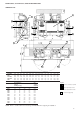
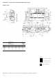
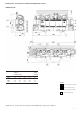
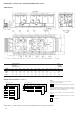
DIMENSIONS, CLEARANCES, WEIGHT DISTRIBUTION (CONT.)
30GX 080-160
NOTE : Refer to certified dimensional drawings 99DI 080GX when designing an installation.
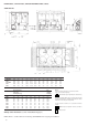
30GX ABCDD2D3EGHJKR
080-090 2882 2200 627 609.6 409.6 609.6 N/A 515 249 128 2300 114.3
105 2882 2200 627 609.6 409.6 609.6 N/A 558 256 120 2300 139.7
115-135 3340 2200 856 609.6 409.6 609.6 N/A 558 256 348.5 2100 139.7
150 4254 2200 627 658.3 1170.5 658.3 2800 497 267 283 N/A 139.7
160 4254 2200 627 658.3 1170.5 658.3 2800 497 267 275 N/A 139.7
Weight distribution Total
at the eight operating
mounting holes (kg) weight (kg)
30GX P1 P2 P3 P4 P5 P6 P7 P8 PT
080 456 583 252 286 252 286 587 708 3410
090 456 583 252 288 252 288 587 712 3420
105 456 645 252 348 252 348 587 770 3658
115 456 689 252 390 252 390 587 813 3829
125 456 700 252 403 252 403 587 824 3877
135 456 703 252 406 252 406 587 827 3889
150 268 166 463 630 403 615 655 990 4189
160 268 166 463 646 403 631 655 1007 4239
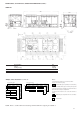
Notes :
1. Unit must have clearances for air flow as follows :
TOP : do not restrict in any way
End and side space required (from solid surface)
2. In case of multiple chillers (up to four units), the respective
clearance between them should be increased from 1830 to
2000 mm for the side space requirement.
3. Unit must have clearances for cooler tube removal as
follows :
Additional space required to remove cooler tubes
Electrical box
Multiple chiller installation (see note 2 and sketch on page 9)