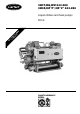
30HT,HQ,HW 043-280 30HZ,HZ"P",HZ"V" 043-280 Liquid chillers and heat pumps PR O C DIA O L N O TR G O L 50 Hz Installation, operation and maintenance instructions QUALITY ASSURANCE SYSTEM 1
CONTENTS Page Start-up checklist .......................................................................................................................................................................... 3 Dimensions/clearances ................................................................................................................................................................. 4 Technical/electrical data ..............................................................................................
START-UP CHECK LIST Equipment sold by: Installed by: Site address: Equipment type and serial numbers: Start-up date: Refrigerant: Supply voltage: Phase imbalance: Ph. 1 V Ph. 2 V Ph. 3 V Current draw: Ph. 1 A Ph. 2 A Ph.
Legend: Dimensions/clearances (mm) B C D E F G H J K Required clearnces for maintenance 1370 1355 1915 1915 1915 1950 2000 915 915 950 950 950 950 1275 1850 2200 2550 2500 2500 2150 2750 750 750 800 800 800 800 1000 600 600 800 800 800 800 800 600 600 800 800 800 800 1000 600 600 800 800 800 800 800 800 800 850 850 850 850 950 710 710 850 900 900 900 900 Power supply Units without condenser 043 2252 1110 052-065 2550 1095 091 2630 1300 101-121 2950 1300 141-161 3350 1300 195-225 4255 13
30H* 091-225 Without condenser B C With condenser Sound enclosure A C Condenser (exc. 30HZ"V" and 30HW) H G K D F J E 30H* 250-280 B C With condenser Sound enclosure Without condenser A ATTENTION : 2 separate power supplies C F J H E D K G Comp. B4 on 30H 280 only Floor mounting - For unit mounting holes, weight distribution and centre of gravity coordinates, refer to the dimensional drawings supplied with the unit. These units are designed for indoor installation.
PHYSICAL DATA 30H* Net nominal cooling capacity** Standard chiller 30HT** 30HW condenserless units*** Standard chiller 30HZ** 30HZ“V” condenserless units Operating weight 30H (with condenser) 30H (without condenser) Refrigerant charge R407-C**** Circuit A Circuit B Refrigerant charge R22**** Circuit A Circuit B Compressors Quantity - Circuit A Quantity - Circuit B Control type No. of capacity steps Minimum step capacity Evaporator Net water volume No.
ELECTRICAL DATA 30H* 043 Power wiring Nominal power supply** V-ph-Hz Nominal voltage range V Auxiliary circuit V-ph-Hz Heater power input 30HT kW Heater power input 30HZ kW Nominal unit power input kW Standard units 30HT Condenserless units 30HW Standard units 30HZ Condenserless units 30HZ“V” Nominal unit operating current A Standard units 30HT Condenserless units 30HW Standard units 30HZ Condenserless units 30HZ“V” Maximum unit power input*** kW Standard units 30HT High condensing pressure/condenserless
APPLICATION DATA Condenser water flow rates 30H* Passes Minimum flow rate, l/s** Closed loop Open loop Maximum flow rate, l/s*** Maximum chilled water flow rate 043 052 065 091 101 111 121 141 161 195 225 250 280 2 2 2 2 2 2 2 2 2 2 2 2 2 1.00 1.20 1.40 2.47 2.54 3.04 3.54 3.54 3.54 4.00 4.46 5.04 5.62 12.30 14.40 16.80 29.70 30.60 36.54 42.48 42.48 42.48 48.00 53.64 60.58 67.52 The maximum chilled water flow (>0,09 l/s per kW or <2.
INSTALLATION Safety considerations Installation, start-up and servicing this equipment can be hazardous due to system pressures, electrical components and equipment location (roofs, elevated structures, etc.). Only trained, qualified installers and service mechanics should install, start-up and service this equipment. Untrained personnel can perform basic functions, such as cleaning coils. All other operations should be performed by trained service personnel.
Water connections Pipe connections After welding the pipes to the flanges previously removed from the water boxes: Refer to the certified dimensional drawings for the sizes and positions of all water inlet and outlet connections. The water pipes must not transmit any radial or axial force to the heat exchangers or any vibration to the pipework or building. a. b. c.
INSTALLATION OF UNITS WITH REMOTE CONDENSERS To ensure optimum and reliable operation of condenserless units (split units for connection to remote condensers) the points listed below must be followed, before connection of these machines to the remote condensers: WARNING: Operation of the chiller with an improper supply voltage or with excessive phase imbalance constitutes abuse which will invalidate the Carrier warranty.
Fill the chilled water circuit with clean water, and an inhibitor formulated specifically for this purpose, or fill it with another non-corrosive fluid to be chilled. Purge air at all high points in the system. If water temperatures below 5°C are likely, add the appropriate volume of ethylene glycol to prevent freezing. Confirm that the suction and discharge line stop valves are fully opened. Open the refrigerant line valves. Check again that the water circuit valves are open.
The units 30H* 043-280 use refrigerant. For your information, we are reproducing here some extracts from the official publication dealing with the design, installation, operation and maintenance of air conditioning and refrigera-tion systems and the training of people involved in these activities, agreed by the air conditioning and refrigeration industry. Refrigerant guidelines Refrigeration installations must be inspected and maintained regularly and rigorously by specialists.
Discharge gas thermostat (DGT) (only for units with low temperature option) A sensor in each compressor discharge line opens to shut down the compressor if the discharge gas temperature exceeds the preset level. Cut out 146°C Cut in 113°C Crankcase heater Each compressor is fitted with an electric resistance crankcase heater which prevents any absorption of refrigerant by the compressor lubricating oil when the compressor is shut down. Each heater is held in place by a screw clip which must be secure.
Preparation of gaskets When rebuilding the cooler, new gaskets must always be used. They must conform to the Carrier specification for compressed gaskets. • • • • • Clean the gasket and its place on the tube sheet. Cover the two matching surfaces (gasket and tube sheet) with adhesive, and stick them together. Let the joint dry for 5 minutes. Moisten the joint with a small amount of compressor oil. Reinstall the evaporator head within 30 minutes.
TROUBLESHOOTING CHART Below we list a series of possible faults, along with the probable causes and suggested solutions. In the event of a unit malfunction, it is advisable to disconnect the power supply and ascertain the cause.