
Specifications


18
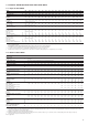
5 - PHYSICAL AND ELECTRICAL DATA FOR UNITS 30GX
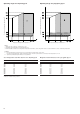
5.1 - Physical data 30GX
30GX 082 092 102 112 122 132 152 162 182 207 227 247 267 298 328 358
Net nominal cooling capacity* kW 282 305 329 384 412 443 500 549 599 705 751 809 916 990 1116 1203
Net nominal cooling capacity*
Option 15LN* kW 277 299 322 377 404 434 490 518 588 677 744 801 907 980 1083 1191
Operating weight kg 3066 3097 3106 3350 3364 3378 3767 3783 4725 5520 5535 6121 6293 7339 7779 7950
Operating weight - option 15LN kg 3566 3597 3606 3922 3936 3950 4443 4459 5653 6462 6477 7191 7363 8521 9011 9268
Refrigerant charge** kg HFC-134a
Circuit A** 52 55 51 51 56 54 71 71 86 124 124 154 169 163 156 169
Circuit B** 53 48 51 50 54 52 66 72 90 81 81 88 104 148 157 167
Oil Polyolester oil CARRIER SPEC. PP 47-32
Circuit A l 20 20 20 20 20 20 20 20 20 40 40 40 40 40 40 40
Circuit B l 20 20 20 20 20 20 20 20 20 20 20 20 20 40 40 40
Compressors Semi-hermetic, twin-screw
Circ. A - nom. size per compressor** 46 46 56 56 66 66 80 80 80+ 66/56 80/66 80/80 80+/80+ 80/80 80/80 80+/80+
Circ. B. nom. size per compressor** 39 46 46 56 56 66 66 80 80+ 80 80 80 80+ 66/66 80/80 80+/80+
Capacity control PRO-DIALOG Plus control
No. of control steps 6 6 6 6 6 6 6 6 6 8 8 8 8 10 10 10
Minimum step capacity % 19 21 19 21 19 21 19 21 21 16 14 14 14 9 10 10
Evaporator Shell and tube with internally finned copper tubes
Net water volume l 50 58 58 69 69 73 65 65 88 126 126 155 170 191 208 208
Water connections Victaulic connections
Inlet/outlet in4445555556666888
Drain and vent (NPT) in 3/8 3/8 3/8 3/8 3/8 3/8 3/8 3/8 3/8 3/8 3/8 3/8 3/8 3/8 3/8 3/8
Max. water side operating pressure kPa 1000 1000 1000 1000 1000 1000 1000 1000 1000 1000 1000 1000 1000 1000 1000 1000
Condensers Copper tubes, aluminium fins
Condenser fans Axial FLYING BIRD 2 fan with a rotating shroud
Quantity 4 4 4 6 6 6 8 8 8 10 10 12 12 14 16 16
Fan speed r/s 15.8 15.8 15.8 15.8 15.8 15.8 15.8 15.8 15.8 15.8 15.8 15.8 15.8 15.8 15.8 15.8
Total air flow l/s 21380 21380 21380 32070 32070 32070 42760 42760 42760 53450 53450 64140 64140 74830 85520 85520
* Standard Eurovent conditions: Evaporator entering/leaving water temperature 12°C and 7°C. Outdoor air temperature 35°C, evaporator fouling factor of 0.000044 m
2
K/W.
** The weights shown are guidelines only. For the unit refrigerant charge please refer to the unit nameplate.
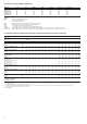
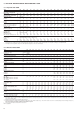
5.2 - Electrical data 30GX
30GX 082 092 102 112 122 132 152 162 182 207 227 247 267 298 328 358
Power circuit
Nominal power supply V-ph-Hz 400-3-50
Voltage range V 360-440
Control circuit supply The control circuit is supplied via the factory-installed transformer
Nominal operating power input* kW 98 108 120 128 149 166 182 198 217 242 285 297 332 370 395 435
Nominal operating power input - option 15LN* kW 99 110 123 130 151 172 185 201 220 248 287 299 329 373 406 447
Nominal operating current drawn * A 170 188 206 220 256 290 313 340 373 413 478 498 547 621 675 744
Maximum power input** kW 132 145 159 177 194 211 232 248 306 318 351 372 459 459 496 612
Circuit A kW - - - - -----194227248306248248306
Circuit B kW - - - - -----124124124153211248306
Cosine phi, unit at full load 0.85 0.85 0.86 0.85 0.85 0.86 0.85 0.85 0.86 0.85 0.85 0.85 0.86 0.85 0.85 0.86
Maximum current drawn (Un - 10%)*** A 248 272 295 331 361 391 433 463 564 593 653 695 847 854 926 1129
Circuit A A - - - - -----361421463564463463564
Circuit B A - - - - -----232232232283391463564
Maximum current drawn (Un)*** A 225 247 268 301 328 355 394 421 513 539 594 632 770 776 842 1026
Circuit A A - - - - -----328383421513421421513
Circuit B A - - - - -----211211211257355421513
Maximum starting current,
standard unit**** (Un) A 338 360 404 437 470 497 592 620 679 1338 1631 1669 1800 1814 1880 2057
Circuit A**** A ---------1127 1420 1459 1544 1459 1459 1544
Circuit B**** A - - - - -----124812481248 1287 1154 1459 1544
Max. starting current/max. current draw
ratio, unit 1.51 1.46 1.51 1.45 1.43 1.40 1.50 1.47 1.32 2.48 2.75 2.64 2.34 2.34 2.23 2.00
Max. starting current/max. current draw
ratio, circuit A - - - - -----3.43 3.71 3.46 3.01 3.46 3.46 3.01
Max. starting current/max. current draw
ratio, circuit B - - - - -----5.93 5.93 5.93 5.01 3.25 3.46 3.01
Max. starting current - reduced
current start**** (Un) A std. std. std. std. std. std. std. std. std. 953 1015 1053 1195 1198 1264 1452
Circuit A A std. std. std. std. std. std. std. std. std. 742 804 843 939 843 843 939
Circuit B A std. std. std. std. std. std. std. std. std. 512 512 512 532 769 843 939
Max.starting current - red. current
start/max. current draw ratio, unit std. std. std. std. std. std. std. std. std. 1.77 1.71 1.67 1.55 1.54 1.50 1.41
Circuit A std. std. std. std. std. std. std. std. std. 2.26 2.10 2.00 1.83 2.00 2.00 1.83
Circuit B std. std. std. std. std. std. std. std. std. 2.43 2.43 2.43 2.07 2.16 2.00 1.83
Three-phase short-circuit holding current kA 25 25 25 25 25 25 25 25 25 N/A N/A N/A N/A N/A N/A N/A
Circuit A kA - - - - -----.25252525252525
Circuit B kA - - - - -----25252525252525
Standby capacity, unit or circuit A†
for evaporator water pump connections kW 4 4 4 5.5 5.5 5.5 7.5 7.5 7.5 7.5 999151515
and for heat reclaim condenser pump kW 3 3 4 4 4 5.5 5.5 5.5 N/A 5.5 7.5 7.5 N/A 9 9 N/A
* Standard Eurovent conditions: Evaporator entering/leaving water temperature 12°C and 7°C. Outdoor air temperature 35°C.
** Power input, compressor and fan, at unit operating limits (evaporator water entering/leaving temperature = 15°C/10°C, outdoor air temperature = 46°C) and a nominal voltage of 400 V (data
given on the unit name plate).
*** Maximum unit operating current at maximum unit power input.
**** Maximum instantaneous starting current (maximum operating current of the smallest compressor(s) + fan current + locked rotor current or reduced starting current of the largest compressor).
Fan electrical data = power input 2.4 kW and current draw 5.5 A per fan.
† Current and power inputs not included in the values above
N/A Not applicable