
Owner's manual


2. Connect piping to the indoor section:
a. Shape tube with a tube bender so that the tube ends
coincide with flare connections.
b. Carefully remove the flare nut fitting from the indoor
section tubing.
c. Thoroughly clean all tubing connection points to pre
vent foreign matter from entering the refrigerant
circuit.
d. Thread the 2 fittings by hand, making sure the threads
fit smoothly and the flare seats evenly against the union.
e. Tighten the 2 fittings securely. If a torque wrench is
used, hold the union side with a wrench and tighten
the nut to the specified torque with torque wrench.
See Table 6 for proper tightening torque.
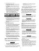
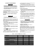
Table 6 — Flare Nut Tightening Torque
FLARE NUT TUBE TORQUE
SIZE (in.) DIAMETER (in.) (ft-lb)
y* V4 10-12
% 35-45
3. Connect piping to the outdoor section:
a. Carefully remove the flare nut from the service valves.
b. If necessary, shape the interconnecting tube with a tube
bender until the tube flare end coincides with the flare
connection on the service valves,
c. Carefully thread the flare nut onto the flare connection
point of the service valve.
d. Tighten the flare nut. See Table 6 for proper tighten
ing torque.
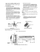
4. Refrigerant line purge procedure:
a. Remove the service valve caps.
b. Use a hex key wrench to carefully rotate the valve stem
of the suction service valve 90 degrees (one-quarter
turn). Leave the valve open for approximately 5 sec
onds, then return the valve to its closed position,
c. Purge refrigerant through the suction valve service port
for 5 seconds, following accepted refrigerant removal
procedure.
d. Rotate the valve stem of the liquid line service valve
^iproximately one-quarter turn counterclockwise. Leave
the valve open for approximately 3 seconds, then re
turn the valve to its closed position.
e. Inspect the refrigerant line connections for leaks using
soapy water or electronic leak detector.
f. If no leaks are found, open both valves. Reinstall ser
vice valve caps.
g. Thoroughly reinspect all joints and connections for re
frigerant leaks. Use soapy water or electronic leak de
tector.
h. Tape both insulated tubing lines together. Begin tap
ing from the bottom of the outdoor section to the point
where the tubing enters the wall. Do not tape too tightly
— this reduces the tubing insulation efficiency.
Step 7 — Connect Condensate Drain Line —
Observe all local sanitary codes when installing condensate
drains.
1. Connect drain lines by inserting a ys-in. ridged PVC pipe
over the drain connection fitting provided.
A CAUTION
The drain tube extension must be securely fastened
to the condensate drain. Failure to do so can result
in condensate water dripping onto the floor.
IMPORTANT: Be sure the drain hose has no slack
which might form a trap. Do not insert a trap in the
drain line, the drain is internally trapped.
3. Insulate the condensate drain line where it is located in or
above an oceupied area with a condensate-proof mate
rial, such as polyurethane or neoprene.
Step 8 — Make Electrical Connections — Be sure
all field wiring complies with local building codes and NEC,
and that the unit voltage is within the limits shown in
Table 7. For units with electric heat option, see Table 8.
Contact local power company for correction of improper
line voltage. Check the unit rating plate for recommended
circuit protection device.
A WARNING
To avoid personal injury or damage to unit, do not make
electrical connections until all power sources are shut
down, locked out, and tagged off. Failure to do so could
result in personal injury or damage to unit.
A CAUTION
Operation of unit on improper line voltage constitutes
abuse and could affect warranty. Refer to Table 7 for
permissible operating limits. Do not install unit in sys
tem where voltage may fluctuate above or below per
missible limits.
NOTE: Use type NM (per NEC) power cable only (pro
vided) between indoor disconnect switch (if installed) and
indoor unit.
NOTE: Install branch circuit disconnect per NEC of ad
equate size to handle unit starting current. Locate diseonnect
within sight from and readily accessible from outdoor unit,
per Section 440-14 of NEC. Some codes allow indoor unit
to share disconnect with outdoor unit if disconnect can be
locked; check local code before installing in this manner.
A WARNING
According to NEC and most local codes, the unit must
have an uninterrupted, unbroken ground to minimize per
sonal injury if an electric fault should occur. The ground
may consist of electrical wire or metal conduit when in
stalled in accordance with existing electrical codes. Fail
ure to follow this warning could result in an electric shock,
fire, or death.
A CAUTION
Do not short circuit the transformer — it is fused. The
transformer can be short circuited by connecting the wrong
wires or by touching a live wire to the side of a grounded
control box.
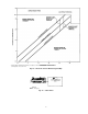
2. To ensure regular flow of condensate water, the drain pipe
should be pitched toward an open drain or sump at a down
ward slope of at least Li-in. per ft. Refer to Fig. 10.
INDOOR SECTION WIRING
1. Remove fan coil unit front cover.
2. Route ground and power wires using NM wire provided.
Remove the factory test leads connected to the power ter
minal block. These leads are for factory testing only and
cannot be used for power connections.
3. Route a 14-gage, 4-wire conductor (cooling only sys
tems) or two 14-gage, 3-wire conductors (heat pump sys
tems) through the power wiring hole in the control box.
NOTE: Connectors are factory supplied.
11