
Owner's manual


combinations, and Table 2 for application range. Refer to
this manual for proper installation of the complete system.
Refer to Table 1 to make sure the correct indoor unit is in
stalled with the correct outdoor unit. Be sure the unit will be
operated within the application guidelines shown in Table 2.
When installing the 38AN or 38BK unit, it is important to
note that for cooling operation when the outdoor air tem
perature is below 55 F, it is necessary to equip the outdoor
unit with the low-ambient accessory.
To install this unit you will need:
1 — 40QNB or 40QNE/H Fan Coil unit with standard wire
less remote controller and indoor unit wire
1 — 38AN or 38BK. Outdoor Unit
1 — Low-Ambient Kit (if required for your application)
NOTE: Field-supplied wire, drain pipe, refrigerant tubing,
etc., are also required to install unit.
The installation materials provided are for use on instal
lations where the indoor section is mounted to gypsum wall
board with wall studs. Other types of applications require
field-supplied mounting hardware. Be sure to follow all in
stallation instructions in this manual carefully in order to achieve
proper unit operation, and be sure that you have all of the
required parts before beginning installation.
Note that the cooling only and heat pump systems utilize
a microprocessor control system to deliver optimum levels
of comfort and efficiency. Refer to Microprocessor Control
Operation section on page 15 for details.
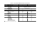
Table 1 — System Combinations for Indoor
and Outdoor Units
SYSTEM
INDOOR
UNIT
OUTDOOR
UNIT
High Wall Cooling Only
40QNB009
40QNB012
38AN009
38AN012
High Wall Heat Pump
40QNE009
40QNH012
38BK009
38BK012
NOTE: A cooling only outdoor unit may not be matched with a heat
pump indoor unit, a heat pump outdoor unit may not be matched with
a cooiing only indoor unit. Do not mismatch systems.
Table 2 — Application Range
COOLING
Maximum Minimum
Indoor Outdoor Indoor Outdoor
95 F DB
71 F WB
115 F DB 67 F DB
57 F WB
55 F DB*
HEATING
Maximum Minimum
Indoor Outdoor Indoor
Outdoor
80 F DB
71 F WB
75 F DB
65 F WB
55FDB 0° F DB
LEGEND
DB — Dry Bulb
WB — Wet Bulb
'Unit may be equipped with a low-ambient control that will allow op
eration down to —20 F.
INSTALLATION
Step 1 — Complete Pre-Installation Checks
UNPACK UNIT(S) — Store unit{s) in original packaging
until moved to the final site for installation. When removing
unit from carton, lift by its 4 comers. Note that there is a
plastic bag containing mounting screws taped to the mount
ing bracket.
INSPECT SHIPMENT — Upon receipt of shipment, in
spect unit (Fig. 1) for damage. Forward claim papers di
rectly to the transportation company. Manufacturer is not re
sponsible for damage incurred in transit.
Check all items (see Table 3), and if any item is missing,
notify your Carrier distributor. To prevent loss or damage,
leave all parts in the original packages until installation.
NOTE: The expansion device is located in outdoor unit.
Step 2 — Select Location — Consult local building
codes and NEC for special installation requirements.
NOTE: There are several ways the unit may be installed in
different types of wall construction. These instructions do
not cover all installation methods. As a typical installation,
these instructions focus primarily on mounting the unit to
wall studs in new construction.
Plan your installation carefully before you begin. Listed
below are some guidelines to follow when determining a lo
cation for the unit;
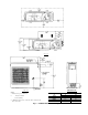
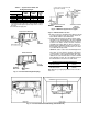
1. Center unit (horizontally) on the wall selected.
2. Allow sufficient space for airflow clearance, wiring, re
frigerant piping, and servicing the unit. See Fig. 2-4.
3. Place the unit so it faces normal location of room
occupants.
TYPICAL FAN COL UNIT
TYPICAL OUTDOOR UNIT
Fig. 1 — Typical Cooling Only/
Heat Pump System